HT21
EN - 10
4.3.4. Diode test
CAUTION
Before taking diode test measurements in circuit remove power from the
circuit being tested and discharge all capacitors.
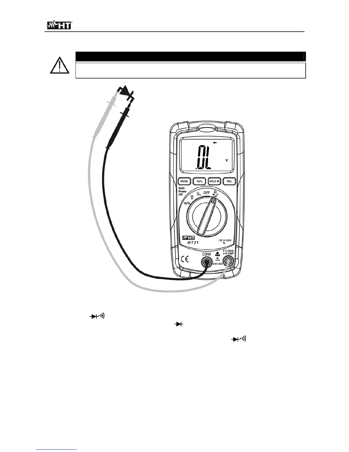
Fig. 5: Using the instrument for diode test
1. Switch on CAP
2. Pressing the MODE key until the symbol is shown at display to meaning the diode
test
3. Insert the test leads into the jacks, the red plug into VHz% CAP jack and black
plug into COM jack (see Fig. 5)
4. Connect the test leads to the diode under test observing the proper polarities indicated
in Fig. 5. The threshold voltage value expressed in mV under this situation is displayed
5. If the threshold voltage value is 0V the diode P-N junction is shorted circuit
6. If the message "O.L" is displayed the diode terminals are reversed, the diode P-N
junction is damaged