HT60
EN - 10
4.3.3. Resistance measurement and Continuity test
CAUTION
Before attempting any resistance measurement, cut off power supply from
the circuit to be measured and make sure that all capacitors are discharged,
if present.
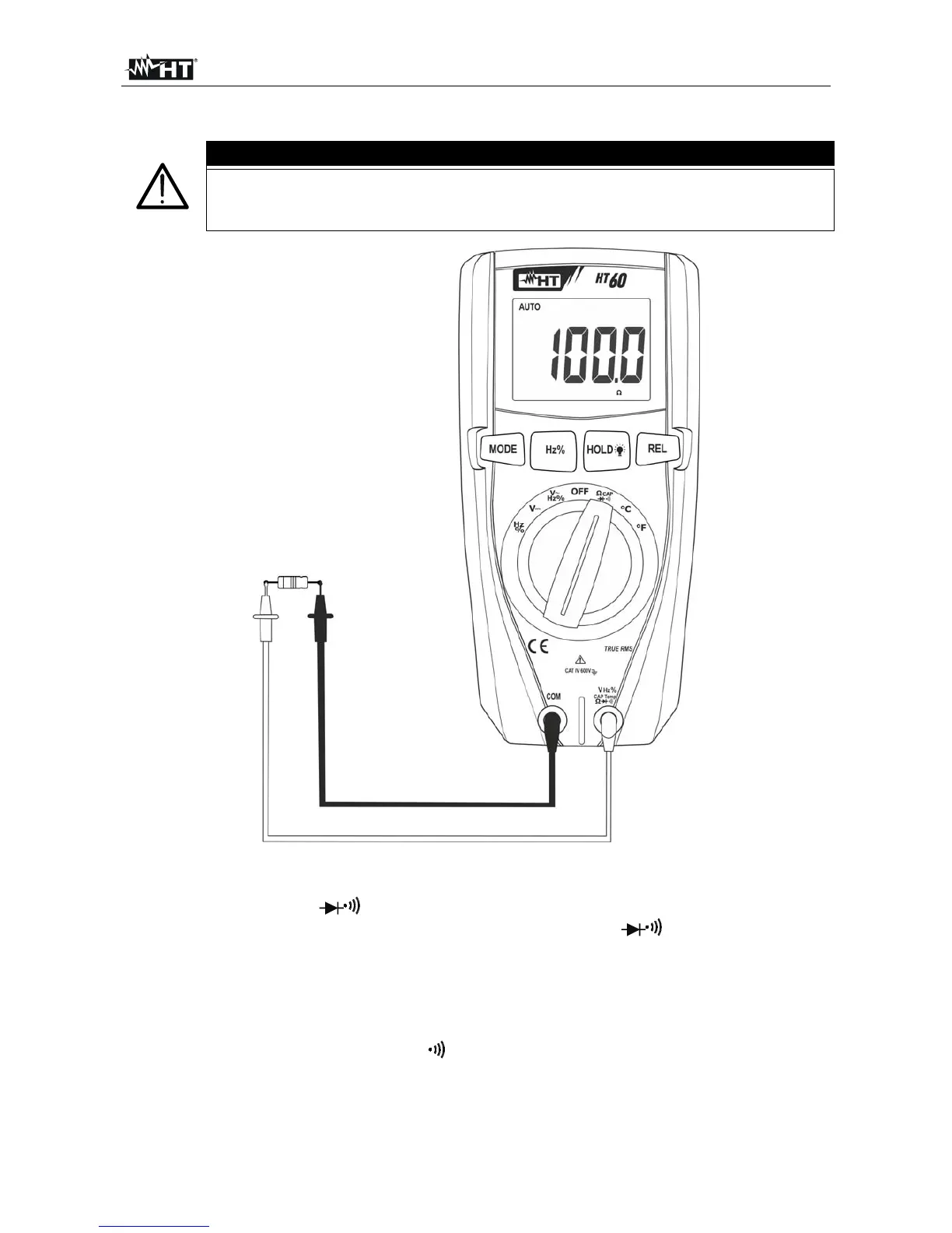
Fig. 4: Use of the instrument for resistance measurement and continuity test
1. Select position CAP
2. Insert the red cable into input terminal VHz%CAPTemp and the black cable
into input terminal COM.
3. Position the test leads in the desired spots of the circuit to be measured (see Fig. 4).
The display shows the value of resistance.
4. The message “O.L.” indicates that the value of resistance exceeds the maximum
measurable value.
5. Press the MODE key until symbol “ ” is shown in order to activate continuity test and
connect the instrument as for Resistance measurement. The continuity buzzer
activates for R<30.
6. To use the HOLD function, see § 4.2.