IRONMETER
EN - 9
4.3.3. Resistance measurement and Continuity test
CAUTION
Before attempting any resistance measurement, cut off power supply from
the circuit to be measured and make sure that all capacitors are discharged,
if present.
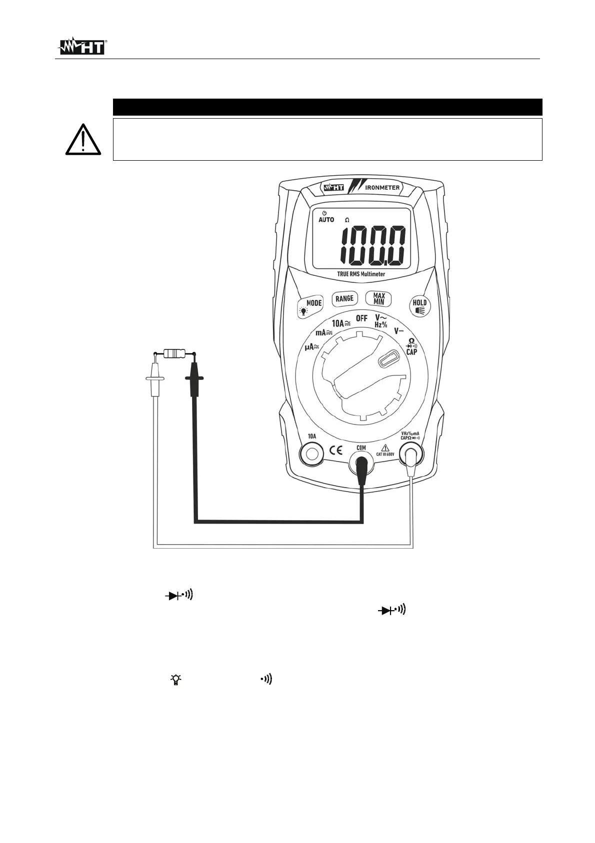
Fig. 5: Use of the instrument for resistance measurement and continuity test
1. Select position
CAP.
2. Insert the red cable into input terminal VHz%mACAP and the black cable into
input terminal COM.
3. Position the test leads in the desired spots of the circuit to be measured (see Fig. 5).
The display shows the value of resistance.
4. If the display shows the message "O.L", select a higher range.
5. Press the MODE/ key to select “ ” measurement, relevant to the continuity test, and
position the test leads in the desired spots of the circuit to be measured.
6. The value of resistance (which is only indicative) is displayed in and the instrument
sounds if the value of resistance is <50
7. To use the HOLD, RANGE and MAX MIN functions, see § 4.2