62
LP-542 REV. 6.2.16
K. 0-10 VOLT INPUT
1. A signal from a building management system may be connected to the boiler to enable remote control. This signal should be a 0-10
volt positive-going DC signal. When the 0-10V input is wired to the boiler terminal strip, a building control system can be used to control
the set point temperature of the boiler. The control interprets the 0-10 volt signal as follows; when the signal is between 0 and 1.5 volts,
the boiler will be in standby mode, not firing. When the signal rises above 1.5 volts, the boiler will ignite. As the signal continues to rise
towards its maximum of 10 volts, the boiler will increase in set point temperature.
2. Connect a building management system or other auxiliary control signal to the terminals marked for this purpose on the boiler
terminal block (shown in Piping Diagrams, this manual). Caution should be used to ensure that the 0-10 VOLT + connection does not
become connected to ground.
NOTE: Ensure that the polarity of the connections from the external modulating boiler controller to the boiler is correct. Reversed
polarity could lead to erratic and/or no response from the boiler controller.
NOTE: Outdoor Temperature Mode Icon on the display will flash if an Outdoor Sensor or 0-10 Volt is not connected to the boiler.
0-10 V INPUT TABLE:
When outside voltage is applied to the connector (2) in the wiring diagram,
1. The Outdoor temperature sensor does not work.
2. Symbol is displayed.
3. The heating temperature is automatically set according with the external voltage input.
NOTE: 0-10V is prioritized over T/T. If input voltage is less than 1.5V then T/T will operate.
The range of input voltage is approximately 1.5[V] ~ 10[V] and the heating temperature settings according to this range are as follows.
Table 27 – 0-10V Input Voltages and Associated Temperatures
Voltage exceeding 15V may damage internal parts. Such damages are not covered by product warranty.
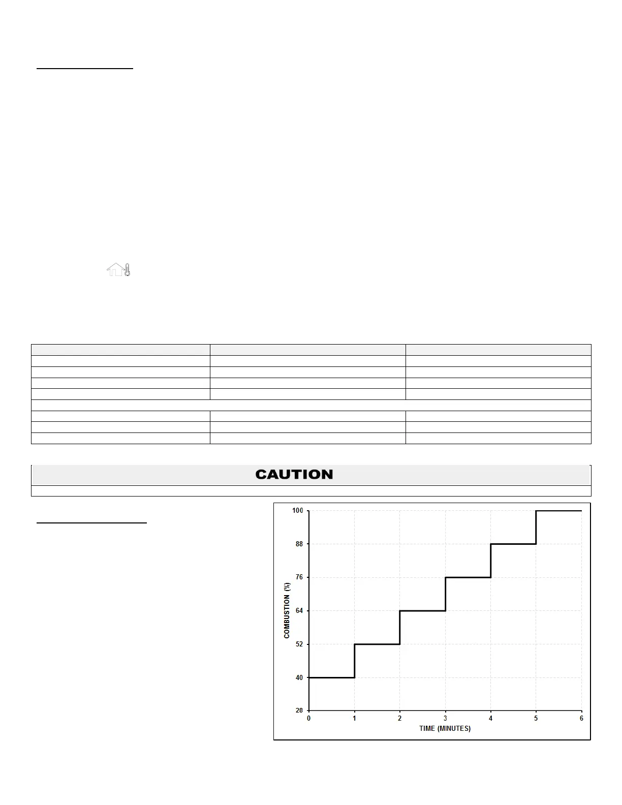
L. STEP MODULATION
When the Step Modulation on/off parameter is active,
step modulation limits the boiler firing rate when a
heating cycle starts. There are six (6) limiting steps
used to limit temperature overshoot and short cycles.
See Figure 51. This feature can be turned on or off
depending on the installation. This parameter can be
changed by the installer by accessing parameter 37:CM
or 38:dM. The control range of this parameter is OFF or ON.
The default value is OFF. The percentage of each step
can be decreased as low as 50% by decreasing the
overall capacity of the boiler in the Installer Menu
changing parameters 18:cb or 19:db.
Figure 51 – Step Modulation

 Loading...