LP-648 Rev. 002 Rel. 002 Date 9.16.20
17
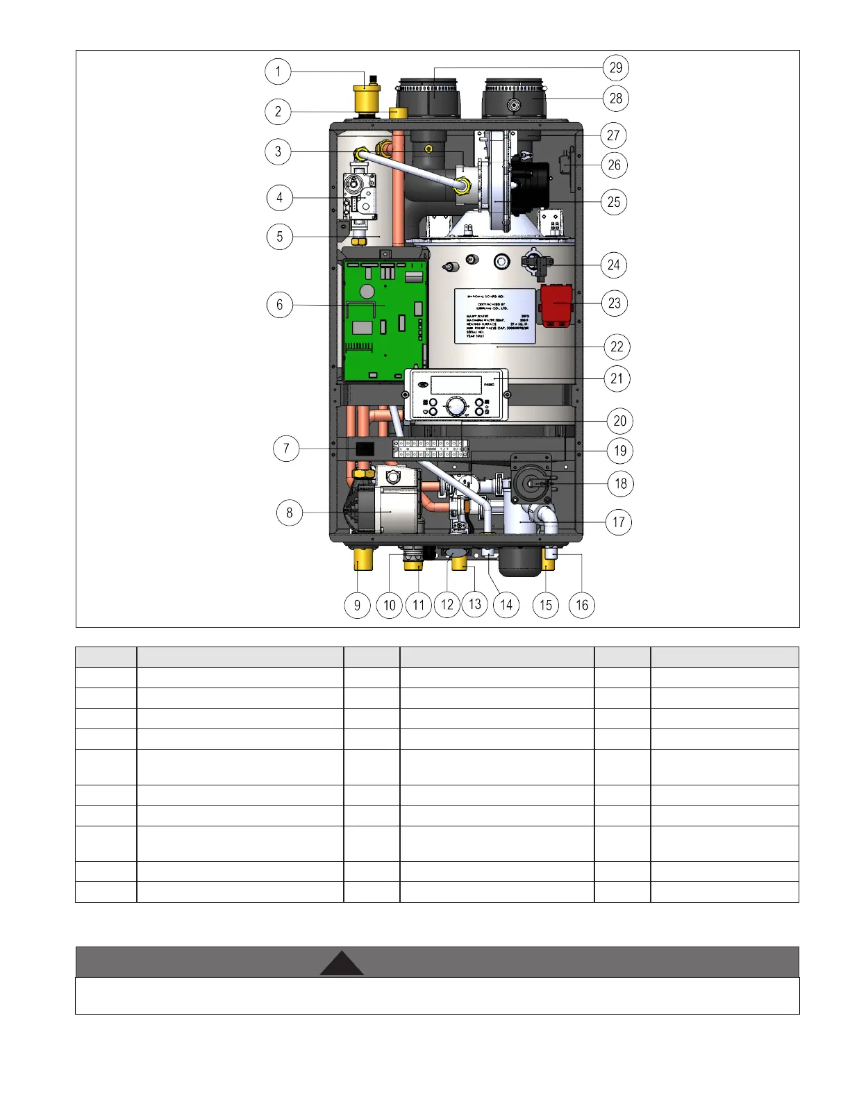
Figure 5 - Components
Number Component Description Number Component Description Number Component Description
1 Air Vent 11 CH Return Adapter 21 Control Panel
2 Relief Valve Adapter 12 CH Pressure Gauge 22 Heat Exchanger
3 Air / Gas Mixing Pipe 13 DHW Outlet Adapter 23 Ignition Transformer
4 Gas Valve 14 Gas Inlet Adapter 24 Flame Detecting Sensor
5 Internal Storage Tank 15
DHW Inlet Adapter with Filter and
Flow Restrictor
25 BLDC Fan
6 Main PCB 16 Condensate Adapter 26 Air Pressure Switch
7 Manual ON/OFF Power Switch 17 Condensate Trap 27 Exhaust Vent Pipe
8
Internal Recirculation Pump (DHW) /
CH Internal Primary Pump
18 Condensate Air Pressure Switch 28 Exhaust Vent Adapter
9 CH Supply Adapter 19 Mixing Valve 29 Air Intake Adapter
10 CH Return Filter 20 Terminal Block
Table 12 - Component List
J. Wall-Mounting (Wall Mount Models Only)
The boiler may be installed on any suitable internal wall (suitable sound-proong may be required when installing onto a stud partition wall).
The boiler must be installed on a wall that can bear its weight (more than 110 lbs. when fully plumbed and full of water). Installing the boiler
on a wall which cannot support its weight could result in property damage, personal injury, or death.