LP-648 Rev. 002 Rel. 002 Date 9.16.20
42
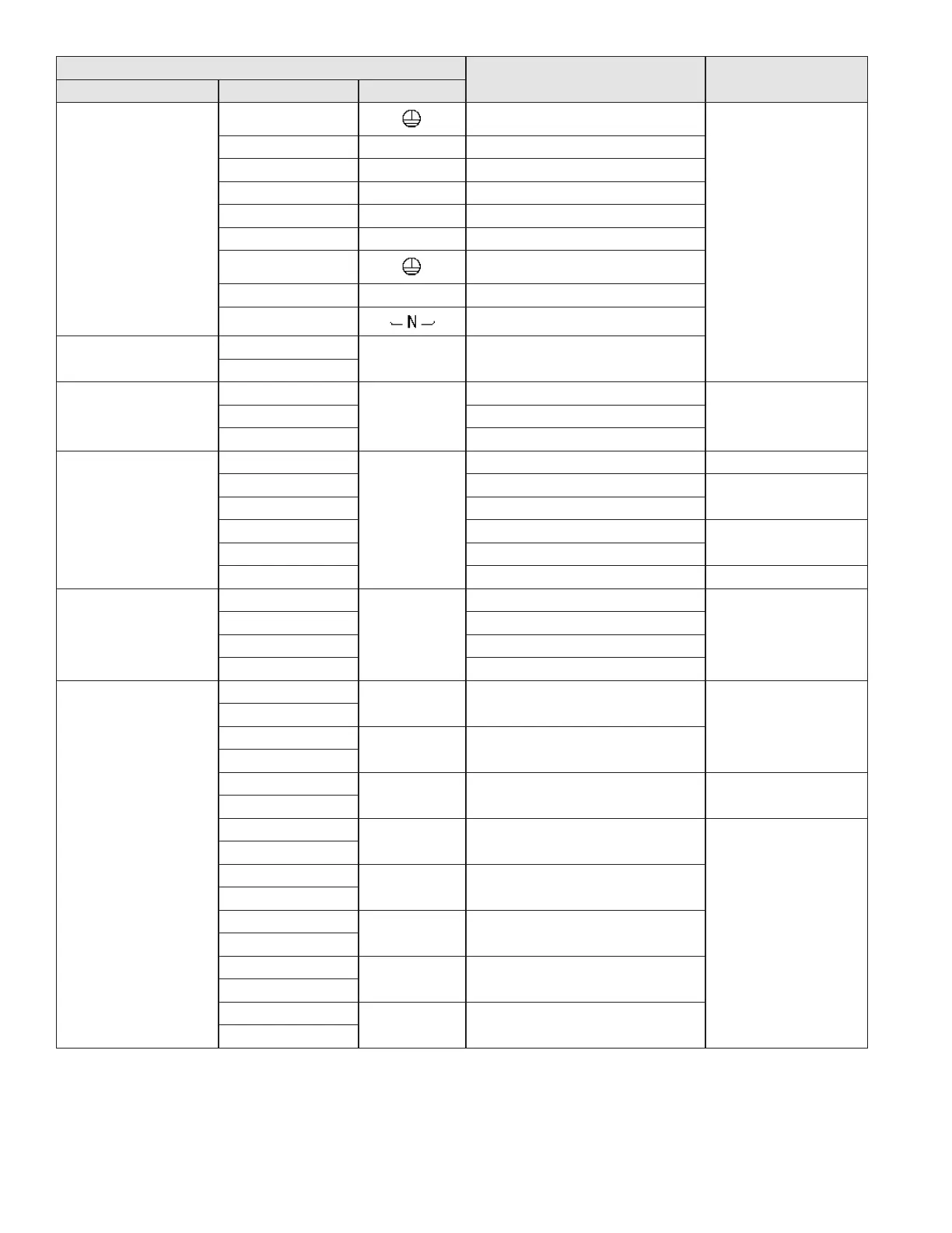
Connector
Description HT Selv
No. of Location Pin Board Silk
CN9
65001WS-12
1 GROUND
HT (120V~) AC
2 L Power Supply Line
3 CP1 External CH Pump Power Supply (Live)
4 IT Ignitor Power Supply
5 L/(HT) Internal Pump Power Supply (Live)
6 GV Gas Valve Power Supply
7 -
8 N Power Supply (Neutral)
9-12 AC Power COM Line
CN6
LW6A4-03
1
CP2/3WAY 3 Way Valve
3
CN1
SMW250-03
1
RS-485
RS-485 +
SELV (5V) DC2 GND
3 RS-485 -
CN4
LWD1140-06
1
FAN
NOT USED -
2 GND
SELV (14V) DC
3 VDD
4 Fan power (start coil)
SELV (8 - 26.5V) AC
5 Fan power (end coil)
6 Fan speed feedback signal SELV (14V) DC
CN8
SMW250-04
1
MCU ISP
GND
SELV (5V) DC
2 ISP / Reset Port
3 ISP TOOL0 Data Port
4 VCC
CN11
LWD1140-16
1
HWL NOT USED
SELV (12V~) AC
8
2
LWL Low Water Level Sensor
10
3
HD Central Heating Demand (T/T) SELV (5V) DC
11
4
TH Display Control
SELV (14V) DC
12
5
APS Flue Air Pressure Switch
13
6
EL NOT USED
14
7
BL Burner High Limit
15
8
HL Condensate Air Pressure Switch
16
Table 21 - Boiler Wiring 1
 Loading...