22
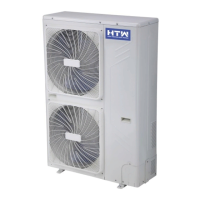
Installation for outdoor unit
Dimension drawing of outdoor unit installation
lnstalling of the connection pipe
Space to the obstruction
Air inlet
Space to the
obstruction
Air outlet
Outdoor unit support
Space to the
obstruction
Air outlet
Right installation feet
Left
installation
feet
Air inlet
Outdoor unit size of shape W1
(W2)*H*D (mm)
A (mm) B (mm)
665(710)x420x280 430 280
600(645)X485X260 400 290
660(710)x500x240 500 260
700(745)x500x255 460 260
730(780)x545x285 540 280
760(810)x545x285 540 280
790(840)x550x290 545 300
800(860)x545x315 545 315
800(850)x590(690)X310
540 325
825(880)x655x310 540 335
900(950)x700x350 630 350
900(950)x795x330 535 350
Length of connection pipe
Added or reduced refrigerant
≤5m
Not needed
5-15m
cc≤12000Btu
20g/m
cc≤18000Btu
30g/m
Connect the Outdoor Unit with Connecting Pipe:
Aim the counter-bore of the connecting pipe at the stop
valve, and tighten the Taper nut with ngers.
Then tighten the Taper nut with a torque wrench. *When
the length of the connecting pipe is changed, extra amount
of refrigerant needs to be added or reduced, so that the
operation and performance of the air conditioner will not
be compromised.
Note: This table is for reference only.
Stop valve
Taper nut Connecting
pipe
Liquid side
pipe
Gas side pipe
Spanner
50cm above
10cm above
30cm above
200cm above
50cm above