7
PrC91
down the middle -
part
of
the V belt by finger
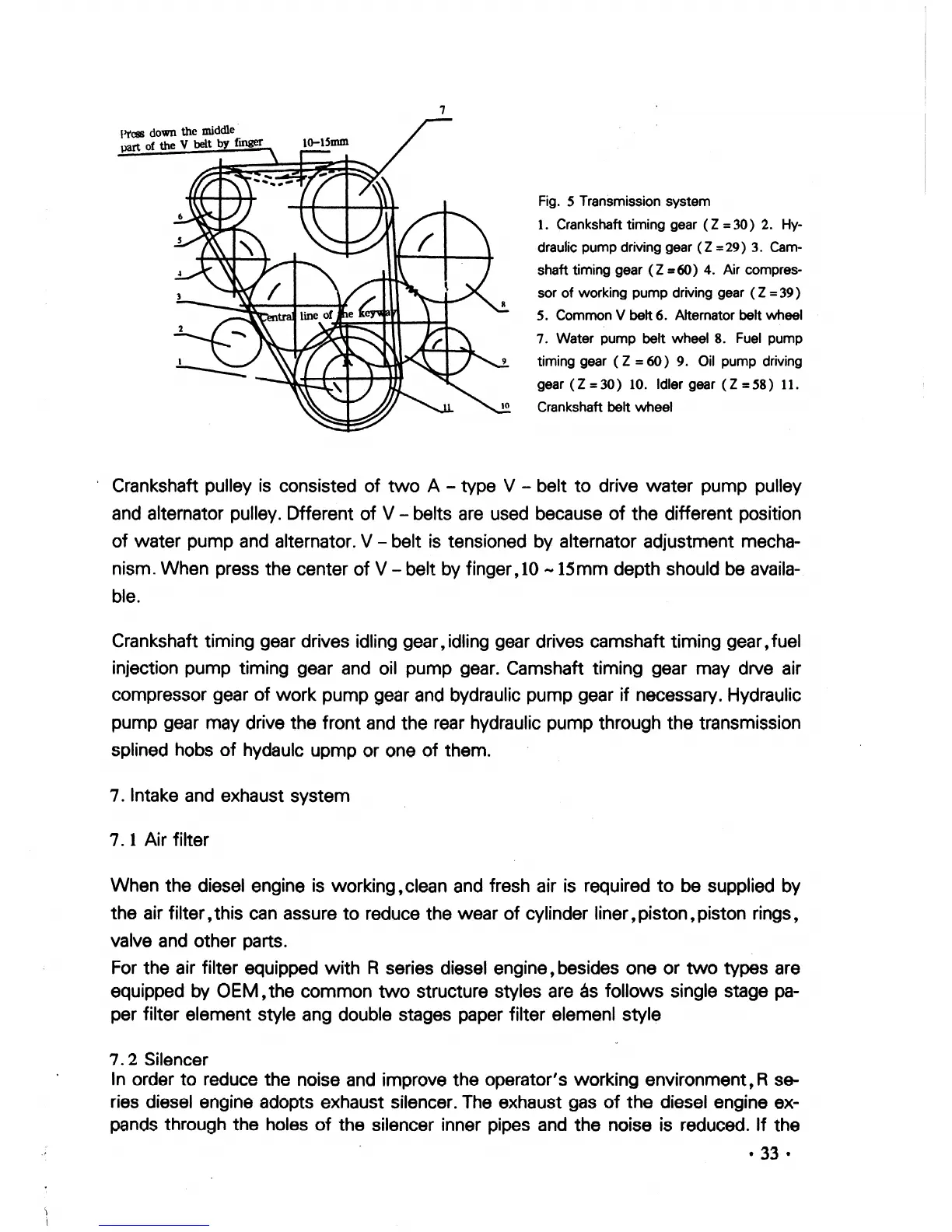
Fig.
5 Transmission system
1.
Crankshaft timing gear
(Z
=30)
2.
Hy-
draulic pump driving gear
(Z
=
29)
3.
Cam-
shaft timing gear
(Z
=60)
4.
Air compres-
sor
of
working pump driving gear
(Z
=
39
)
5.
Common V belt 6. Alternator belt wheel
7.
Water pump belt wheel
8.
Fuel
pump
timing gear
(Z
=
60)
9.
Oil
pump driving
gear
(Z
=30)
10.
Idler gear
(Z
=58)
11.
Crankshaft belt wheel
, Crankshaft pulley is consisted
of
two
A - type V - belt
to
drive
water
pump
pulley
and
alternator pulley. Dfferent
of
V - belts are used because
of
the different position
of
water
pump
and alternator. V- belt is tensioned by alternator adjustment mecha-
nism.
When
press
the
center
of
V - belt by finger,
10
-15mm
depth should
be
availa-
ble.
Crankshaft timing gear drives idling gear,idling gear drives camshaft timing gear,fuel
injection
pump
timing gear and oil
pump
gear. Camshaft
timing
gear may drve air
compressor gear
of
work
pump
gear and bydraulic
pump
gear if necessary. Hydraulic
pump
gear may drive
the
front
and the rear hydraulic pump through
the
transmission
splined
hobs
of
hydaulc
upmp
or
one
of
them.
7. Intake and exhaust
system
7. 1 Air filter
When
the
diesel
engine
is working,clean and fresh air is required
to
be supplied by
the
air
filter,
this can assure
to
reduce
the
wear
of
cylinder liner,piston t piston rings,
valve and other parts.
For
the
air filter equipped
with
R series diesel engine, besides
one
or
two
types are
equipped by
OEM,
the
common
two
structure styles
are
as
follows
single stage
pa-
per filter element style ang double stages paper filter elemenl style
7. 2 Silencer
In order
to
reduce
the
noise and improve
the
operator's
working
environment,R
se-
ries diesel engine adopts exhaust silencer. The exhaust gas
of
the
diesel engine ex-
pands through
the
holes
of
the
silencer inner pipes and
the
noise is reduced.
If
the
• 33 •
 Loading...