13
14
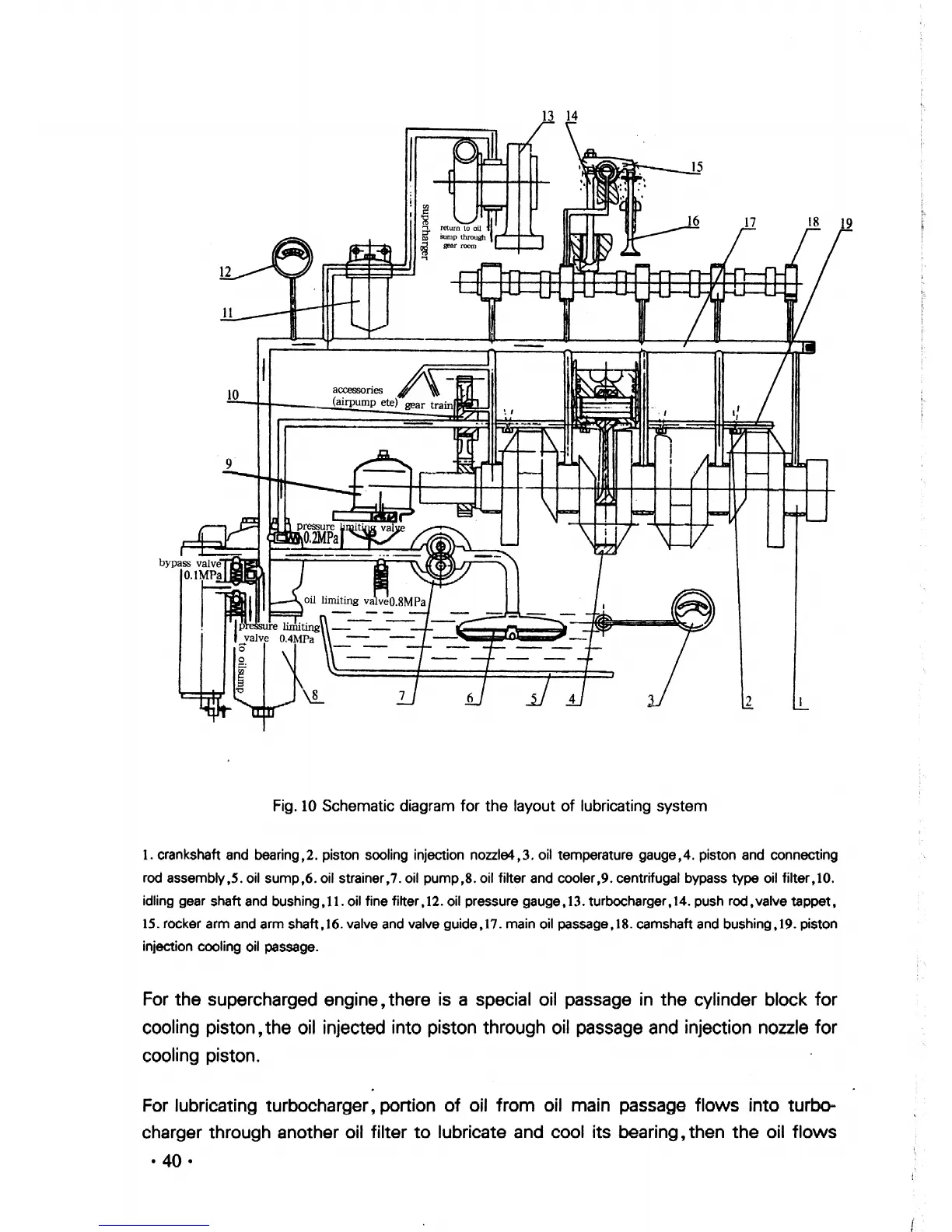
Fig.
10
Schematic diagram for the layout
of
lubricating system
1.
crankshaft
and bearing;2. piston sooling injection nozzle4;3. oil temperature gauge;4. piston
and
connecting
rod
assembly,S. oil sump,6.oil strainer,7.oil pump,8.oil filter and cooler,9.centrifugal bypass
type
oil filter;10.
idling gear shaft and bushing,
11.
oil fine filter,12. oil pressure gauge,
13.
turbocharger,14. push rod,valve
tappet,
15.
rocker arm and arm shaft,16. valve and valve
guide,
17
. main oil passage,
18.
camshaft and bushing,19. piston
injection cooling oil passage.
For the supercharged engine, there is a special oil passage
in
the cylinder block for
cooling piston,the oil injected into piston through oil passage and injection nozzle for
cooling piston.
For lubricating turbocharger, portion
of
oil from oil main passage flows into turbo-
charger through another oil filter
to
lubricate and cool its bearing, then the oil flows
• 40 •


 To Next Page