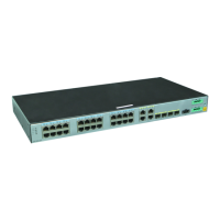
Figure 3-64 AR511GW-LM7 appearance
1
8-36 V; 4 A
12
34
OTG
CONSOLESATA
RESET
micro SD
G
P
S
W
I
F
I
1
W
I
F
I
0
3
G
/
L
T
E
-
D
I
V
3
G
/
L
T
E
-
M
A
I
N
1
2
GE0
3 5122
7 8 9 10 11
4 6
1
Power jack
NOTE
Use a DC power cable to connect the router
to an external power source.
2 USB interface (host)
3 GPS antenna interface 4 3G/LTE antenna interface
5 WAN interface: one GE electrical
interface
6 Two Wi-Fi antenna interfaces
7 USB interface (OTG) 8 Two SIM card slots
NOTE
l The SIM card slots support double-card
single-standby.
l The router must use industrial SIM cards.
l The mounting hole above the SIM card
slots is used to fix the SIM card cover
with a screw.
9 Micro SD card slot 10 CONSOLE interface
Huawei
AR500&AR510&AR531&AR550&1500&AR2500
Industrial Switch Routers
Hardware Description
3 Chassis
Issue 10 (2019-03-06) Copyright © Huawei Technologies Co., Ltd. 361
 Loading...