Do you have a question about the Huawei BBU3900 V300 and is the answer not in the manual?
Describes installation in specific cabinet types.
Describes installation in PS4890 cabinets.
Details installation within a standard 19-inch rack.
Covers installation in APM30H (Ver.B).
Explains installation within the TMC cabinet.
Details installation in the RRU3004 rack.
Explains installation in TMC11H (Ver.B).
Covers installation in APM30H (Ver.B, +24V).
Details wall-mounting installation procedures.
Explains installation in the OMB.
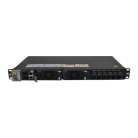
Describes the physical dimensions and appearance of the BBU.
Explains how BBU boards are configured and installed.
Describes the physical installation of the BBU unit.
Details the connection of various cables to the BBU.
Illustrates and lists the connections for BBU cables in APM30H(Ver.A).
Details the specific connection of the monitoring signal cable.
Specifies the physical space needed for installation.
Describes how to mount the BBU unit into the rack.
Details the installation of the DCDU-03B component.
Describes mounting the DCDU-03B within the TMC.
Details the process of installing the BBU unit itself.
Details mounting the DCDU-03B into the cabinet.
Describes the physical installation of the BBU unit.
Details how to mark anchor points for installation.
Covers the process of drilling and installing fasteners.
Describes the assembly and installation of the H-shaped stand.
Explains how to remove specific washers during installation.
Details aligning and inserting the rack into the stand's slots.
Describes securing the bottom section of the RRU3004 rack.
Covers the installation of adapter components.
Details mounting the BBU unit into the rack assembly.
Describes installing the DCDU-03B with -48V power.
Details attaching mounting ears to the IMB03.
Describes the process of installing mounting bolts.
Covers the physical mounting of the IMB03.
Explains how to firmly secure the installed IMB03.
Steps to prepare for RRU installation.
Describes attaching the main bracket for the RRU.
Details the physical mounting of the RRU.
Explains how to firmly secure the installed RRU.
Specifies clearance and spacing for wall mounting.
Details attaching mounting ears suitable for wall mounting.
Describes how to mark the wall for mounting holes.
Covers the process of installing wall expansion bolts.
Details securing the BBU unit to the wall.
Describes mounting the DCDU-03B case for wall installation.
Details the cable connections for the wall-mounted BBU.
Describes mounting the BBU unit into the cabinet.
Illustrates and lists the cable connections for the BBU.
Details the connection of power and optical cables.
Details the connection of E1/T1 and FE/GE cables.
Details the monitoring signal cable connection.
Describes mounting the BBU and SLPU into the cabinet.
Details the BBU power cable connection.
Describes mounting the BBU and SLPU into the cabinet.
Details connection of monitoring and in-position signal cables.
Details various BBU cable connections for this configuration.
Details attaching brackets and the mounting plate to a pole.
Describes mounting the BBU case into the OMB.
Details the installation of PGND cable as an example.
Details the input power cable connection for DC and AC OMBs.
Details the BBU power cable connection for DC and AC OMBs.
Details the E1/T1 cable installation.
Details the FE/GE cable and CPRI optical cable installation.
Describes how to configure DIP switches on the BBU.
Provides pinout details for BBU signal cables.
| Type | Baseband Unit |
|---|---|
| Category | Network Hardware |
| Model | BBU3900 V300 |
| Vendor | Huawei |
| Power Supply | -48 V DC |
| Storage Temperature | -40°C to +70°C |
| Relative Humidity | 5% to 95% |
| MTBF | > 200, 000 hours |
| Frequency Bands | Supports multiple frequency bands |
| Operating Temperature | -40°C to +55°C |
| Input Voltage | -48 V DC |
| Installation | 19-inch rack mount |
| Interface Type | CPRI |
| Supported Protocols | Ethernet |
| Dimensions | 442 mm x 220 mm x 88 mm |