Prerequisite
l The tools and materials, such as an ESD wrist strap or ESD gloves and screwdriver, are
ready.
l The quantity and type of board to be replaced are confirmed. For details, see 5.1 Querying
Board Information.
l The authorized personnel are permitted to enter the site. The required keys are available.
Context
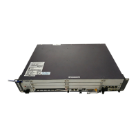
l Figure 5-14 shows the position of the USCU in the BBU.
Figure 5-14 Position of the USCU
USCUUSCU
ALMALM
RUNRUN
ACTACT
TOD1TOD1
GPS
RX+ RX- TX+ TX-
BITS
GREEN IN
YELLOW OUT
RGPS
M-1PPS
TOD0
GPS
RX+ RX- TX+ TX-
BITS
GREEN IN
YELLOW OUT
RGPS
M-1PPS
TOD0
1S+ 1S- GND PWR1S+ 1S- GND PWR
USCU
l The board is hot-swappable.
Procedure
Step 1 Wear an ESD wrist strap or a pair of ESD gloves.
WARNING
Take proper ESD protection measures, for example, wear an ESD wrist strap or a pair of ESD
gloves, to prevent electrostatic damage to the boards, modules, or electronic components.
Step 2 Record all the cable connections on the panel of the board to be replaced.
Step 3 Disconnect the GPS clock signal cable from the USCU, as shown in Figure 5-15.
Figure 5-15 Disconnecting cables
Step 4 Remove the two M3 screws on the panel, and then remove the USCU, as shown in Figure
5-16.
5 Replacing Components of the BBU3900
BBU3900
Hardware Maintenance Guide
5-14 Huawei Proprietary and Confidential
Copyright © Huawei Technologies Co., Ltd.
Issue 03 (2010-06-05)
 Loading...

