Context
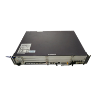
l Figure 5-20 shows the position of the optical module on a board.
Figure 5-20 Position of the optical module
1
(1) Optical module
l The optical module is hot-swappable.
Procedure
Step 1 Wear an ESD wrist strap or a pair of ESD gloves.
CAUTION
Take proper ESD protection measures, for example, wear an ESD wrist strap or a pair of ESD
gloves, to prevent electrostatic damage to the boards, modules, or electronic components.
Step 2 Choose the optical module of the same type as the faulty optical module according to the label
on the module.
Step 3 Record the position of the faulty optical module on the board.
Step 4 Press the latch on the optical cable connector, and then remove the connector from the faulty
optical module, as shown in Figure 5-21.
5 Replacing Components of the BBU3900
BBU3900
Hardware Maintenance Guide
5-18 Huawei Proprietary and Confidential
Copyright © Huawei Technologies Co., Ltd.
Issue 03 (2010-06-05)
 Loading...

