7
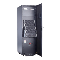
Tower-mounting the PDU
b
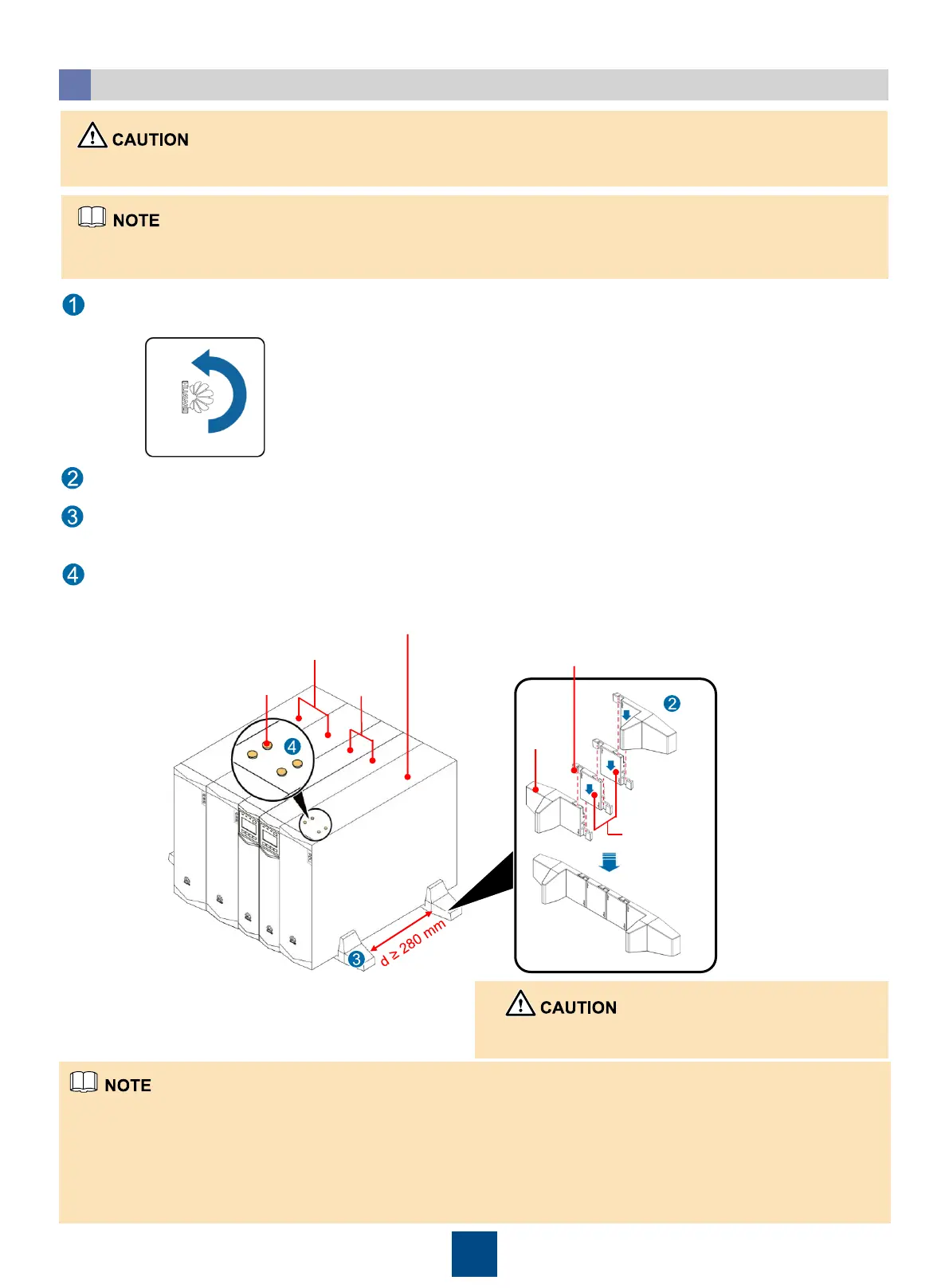
After the PDU is tower-mounted, seal the four screw holes on the top with rubber plugs that are delivered with the PDU.
Install the PDU front panel, when you change from rack mounting to tower mounting, rotate the logo anticlockwise 90
degrees.
b
Install two support bases for each group of devices. Place the support bases on the floor, determine the distance (greater
than or equal to 280 mm) between the support bases, place devices on the support bases, and secure them.
Assemble support bases. When you assemble two support bases, align connecting buckles with holes and insert the
buckles vertically, as shown in the following figure.
Rubber plugs
3 U PDC-0091V2ACIOA
2 U UPSs
3 U battery packs
Components
installed
between
support
bases
Support
base
Connecting
buckle
When you tower-mount the PDU, place it horizontally during cable connection. Stand it upright after cable installation.
1. The support base length is adjustable. You can add components to increase the length.
2. Exert force to disassemble components in the reverse directions of assembling.
1. The support base length is adjustable. You can add components to increase the length. A component (1 U) installed
between the support bases is required for a 3U device. No component installed between the support bases for a 2U
device.
2. The minimum distance between two support bases should be 280 mm and the maximum should not exceed the edge of
the device. It is recommended that the distance between the front (rear) base and the front (rear) side of the device
should be about 100 mm.
When to disassemble components use protective
gloves to protect hands.
 Loading...