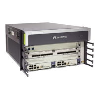
The HUAWEI NetEngine40E Universal Service Router, specifically the DPD300-4-12 Power Distribution Box, is designed to manage power distribution for network equipment. This device supports dual-two inputs, allowing for redundant power feeds and flexible power configurations for NE40E-X8 and NE40E-X3 series routers.
Function Description
The DPD300-4-12 Power Distribution Box serves as a central power management unit, distributing power from input sources to multiple Power Equipment Modules (PEMs) or Power Modules (PWRs) within the connected network equipment. It features distinct input and output areas for both "A" and "B" power feeds, enabling the separation and management of power paths.
For the NE40E-X8, the power distribution box supports various configurations. In "Power distribution mode 1," it can power two NE40E-X8s simultaneously. For the first NE40E-X8, PEM-A1 and PEM-A2 connect to A1-1 and A1-2 respectively, while PEM-B1 and PEM-B2 connect to B1-1 and B1-2. If a second NE40E-X8 is connected, its PEM modules utilize the A2-1, A2-2, B2-1, and B2-2 outputs. "Power distribution mode 2" for the NE40E-X8 shows a similar setup, with PEM-A1 and PEM-A2 for the first NE40E-X8 connected to A1-1 and A1-2, and PEM-B1 and PEM-B2 connected to B1-1 and B1-2. The second NE40E-X8 would then use the A2-1, A2-2, B2-1, and B2-2 outputs for its PEM-A1, PEM-A2, PEM-B1, and PEM-B2 modules respectively.
For the NE40E-X3, the power distribution box is designed to work with two PWR modules. PWR 1 connects to any power output in the OUTPUT A area, and PWR 2 connects to any power output in the OUTPUT B area of the power distribution box. This flexibility allows for efficient power allocation based on the specific needs of the NE40E-X3.
The device includes multiple output terminals, each with designated NEG(-) and RTN(+) connections, ensuring proper polarity for the connected equipment. The clear labeling of input and output terminals (e.g., A1-1, A1-2, A1-3, A2-1, A2-2, A2-3, B1-1, B1-2, B1-3, B2-1, B2-2, B2-3) facilitates correct wiring and troubleshooting.
Important Technical Specifications
The DPD300-4-12 Power Distribution Box is designed for robust performance and includes several key technical specifications related to its components and cabling:
- Input Cable Specifications:
- Wire: 450/750V, 60227 IEC 02(RV) 150mm^2, blue, 360A (per meter).
- Wire: 450/750V, 60227 IEC 02(RV) 150mm^2, black, 360A (per meter).
- Naked Crimping Terminal: JG, 150mm^2, M12, Tin Plating (8 pieces).
- Output Cable Specifications:
- Power Cable: 450/750V, H07Z-K UL3386, 16mm^2, blue, Low Smoke Zero Halogen Cable (per meter) (12 pieces).
- Power Cable: 450/750V, H07Z-K UL3386, 16mm^2, black, Low Smoke Zero Halogen Cable (per meter) (12 pieces).
- Naked Crimping Terminal: JG2, 16mm^2, M6, 95A, Tin Plated, for OEM (48 pieces).
- Grounding Cable Specifications (Equipment Room):
- Wire: 450/750V, 60227 IEC 02(RV) 50mm^2, yellow green, 170A (per meter) (1 piece).
- Terminal: Naked Crimping Terminal, JG, 50mm^2, M10, Tin Plating (1 piece).
- Grounding Cable Specifications (Cabinet):
- Power Cable: 450/750V, H07Z-K UL3386, 25mm^2, Yellow Green, Low Smoke Zero Halogen Cable (per meter) (1 piece).
- Terminal 1: Naked Crimping Terminal, JG2, 16mm^2, M6, 95A, Tin Plated, for OEM (1 piece).
- Terminal 2: Naked Crimping Terminal, OT, 25mm^2, M8, Tin Plating, Naked Ring Terminal (1 piece).
- Fasteners and Tools:
- Panel bolt: M6 (4 pieces).
- Captive nut: 4 pieces.
- Slide rail: 2 pieces.
- Torque specifications for various screws:
- M5: 30±3kgf.cm
- M3: 3±0.3kgf.cm
- M6: 30±3kgf.cm (for fixing the power distribution box)
- M10: 150±15kgf.cm (for grounding cables)
- M8: 80±8kgf.cm (for grounding cables)
- M6: 50±5kgf.cm (for grounding cables and power output cables)
- M12: 260±26kgf.cm (for power input cables)
Usage Features
The DPD300-4-12 is designed for ease of installation and reliable operation within a cabinet environment.
- Cabinet Integration: The power distribution box is installed into a standard cabinet, typically an N68E, with slide rails for easy mounting. The installation process involves securing slide rails 7U below the top of the power distribution box and installing captive nuts for stability.
- Cable Management: The design emphasizes organized cable routing. Power input cables are passed through holes on the cabinet top and connected to the power distribution box. Power output cables are laid out along two mounting bars at the back of the cabinet and connected to the respective devices. This systematic approach helps maintain a tidy and efficient cabinet layout, reducing clutter and improving airflow.
- Protective Plates: The device includes protective plates for connecting terminals. These plates must be temporarily removed during installation for wiring and then re-installed to ensure safety and prevent accidental contact with live terminals.
- Dual-Two Inputs: The "Dual-Two Inputs" feature provides redundancy and flexibility. It allows for two separate power input sources, enhancing reliability by ensuring that if one source fails, the other can continue to power the connected equipment. This is crucial for maintaining high availability in network infrastructure.
- Support for Multiple Devices: The power distribution box can power multiple NE40E-X8s or NE40E-X3s, making it a versatile solution for expanding network capacity within a single cabinet.
Maintenance Features
Maintenance of the DPD300-4-12 primarily focuses on circuit breaker replacement, ensuring the continued safe operation of the power distribution system.
- Circuit Breaker Replacement: The device allows for the replacement of individual air breakers. This is a critical maintenance task that can be performed to address faulty breakers or to upgrade them if necessary.
- Safety Precautions: Before any maintenance, it is imperative to power off the power distribution box and remove all metal ornaments (watches, rings) to prevent electrical shock. New circuit breakers must be switched off before installation.
- Procedure:
- Identify the location of the air breaker to be replaced.
- Ensure all circuit breakers are switched off.
- Tear down the plastic panel of the power distribution box using a crosshead screwdriver.
- Remove the air breaker to be replaced.
- Install a new air breaker into the power distribution box.
- Re-install the plastic panel for the power distribution box.
- Tool Requirements: Standard tools such as a crosshead screwdriver, socket wrench, ladder, marker, and torque batch are required for installation and maintenance. The use of a torque batch is essential to ensure that all fasteners are tightened to the specified torque values, preventing loose connections and ensuring electrical safety.
- Heavy Component Handling: The power distribution box is heavy and requires two people for installation, highlighting the need for proper handling procedures to prevent injury and damage to the equipment.
- Documentation: The manual provides clear figures and step-by-step instructions for installation and maintenance, which are crucial for technicians to perform tasks correctly and safely. The detailed material list ensures that all necessary components and tools are available before starting any procedure.