Do you have a question about the Huawei OptiX RTN 950 and is the answer not in the manual?
Covers general safety, local regulations, personnel qualifications, personnel and device safety.
Guidelines for handling boards using ESD protection and proper grip techniques.
Safety advice for handling power cable terminals to prevent damage.
Identifies ports and indicators on the front panel of the RTN 905 1E.
Identifies ports and indicators on the front panel of the RTN 905 2E.
Identifies ports and indicators on the front panel of the RTN 910A.
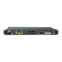
Identifies ports and indicators on the front panel of the RTN 950.
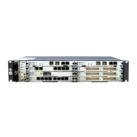
Identifies ports and indicators on the front panel of the RTN 950A.
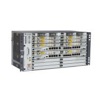
Identifies ports and indicators on the front panel of the RTN 980.
Shows cabinet views and lists technical specifications like dimensions and temperature.
Details internal components of the APM30H cabinet with AC power supply.
Details internal components of the TMC11H cabinet with DC power supply.
Specifies required installation dimensions and clearance around the cabinet.
Illustrates APM30H cabinet installation on a base and in a stacked configuration.
Steps for casting a concrete pad, marking anchor points, and drilling holes for the base.
Procedure for installing expansion bolts, positioning, and adjusting the base level.
Steps for moving the cabinet onto the base and securing it with bolts.
Details on securing the cabinet onto the base using bolts and washers.
Instructions for stacking cabinets, including removing covers and securing bolts.
Scenario for installing RTN 900 in APM30H cabinet with AC power.
Scenario for installing RTN 900 in TMC11H cabinet with DC power.
Installing RTN 900 in APM30H for outdoor use with AC power.
Installing RTN 900 in TMC11H for outdoor use with DC power.
Procedure for fixing floating nuts for RTN 900 installation in cabinets.
Steps for installing the RTN 900 unit into the cabinet using guide rails.
Details UELP and UFLP board specifications and SLPU functions.
Procedure for installing the SLPU unit, including handling extra UELP boards.
Describes SOU as an optional AC power component with different outlet types.
Steps for installing the SOU and connecting its power cable.
Details heater installation, location, and temperature-controlled operation.
Procedure for connecting the power cable for the heater in APM30H and TMC11H cabinets.
Procedures for installing PGND cables for both the cabinet and the equipment.
Steps for connecting the AC input power cable to the APM30H cabinet, including protective cap handling.
Instructions for installing power cables for RTN 900A/950/950A, RTN 905, and RTN 980.
Procedure for installing power cables for IBBS200D/IBBS200T battery cabinets.
Procedure for installing power cables for the fan assembly in the IBBS200D battery cabinet.
Procedure for installing power cables for heating films in the IBBS200D battery cabinet.
Procedure for installing power cables for the TEC in the IBBS200T battery cabinet.
Steps for connecting the DC input power cable to the TMC11H cabinet.
Procedure for installing power cables for the RTN 900 within the TMC11H cabinet.
Illustrates how service cables are routed within APM30H/TMC11H cabinets and notes exceptions.
Procedure for installing E1 cables, including notes on cabinet sharing and routing methods.
Procedure for installing Ethernet cables, including notes on cabinet sharing and routing methods.
Procedure for installing IF cables, with warnings and board-specific instructions.
Procedure for installing optical fibers, including routing and protection.
Procedure for connecting signal monitoring cables to CCUB/CSHU/CSHUA boards, including pin mapping.
Procedure for installing cascading cables when multiple RTN 905 devices are in a single cabinet.
Details the left and right cable outlet modules on the APM30H/TMC11H cabinets.
Demonstrates the method for sealing the cable outlet bags.
Steps for applying baffle plates and fireproof mud to seal cable holes on the cabinet base.
Steps for installing batteries, including warnings and securing baffle plates.
Procedure for installing power cables for batteries, including copper bars and connections.
Checklist for verifying cabinet installation compliance, security, and dimensions.
Checklist for ensuring the installation environment is clean and neat.
Checklist for PGND cables, power connections, wire stripping, lugs, washers, and cable binding.
Process for checking power-on status of AC/DC supplies, indicators, and voltages.
Procedure for closing and locking the cabinet door to prevent rust.
Detailed procedure for assembling the power series 120 connector, including stripping and crimping.
Detailed procedure for assembling the EPC4 connector, including conductor insertion and securing.
Steps for using an extraction tool to remove and replace fuses in the EPU.
Provides color codes (Huawei & International) for cabinet and base paint matching.
Instructions for polishing, cleaning, applying paint, drying, and quality checking for paint repair.
| Brand | Huawei |
|---|---|
| Model | OptiX RTN 950 |
| Category | Microphone system |
| Language | English |