Do you have a question about the Huawei OptiX RTN 905 and is the answer not in the manual?
Covers general safety instructions, local regulations compliance, and personnel qualification requirements.
Highlights risks from high-voltage power supply and radio frequency signals, and safety measures.
Focuses on electrical connection checks, proper grounding, and protection against electrostatic discharge.
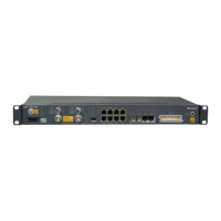
Illustrates and labels the front panel interfaces of the RTN 905 1A model.
Illustrates and labels the front panel interfaces of the RTN 905 2A model.
Illustrates and labels the front panel interfaces of the RTN 905 1C model.
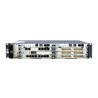
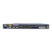
Illustrates and labels the front panel interfaces of the IDU 905 1E model.
Illustrates and labels the front panel interfaces of the IDU 905 2E model.
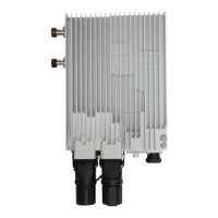
Displays the front appearance and technical specifications of the OMB cabinet.
Shows the left side appearance of the OMB cabinet.
Displays the right side appearance of the OMB cabinet.
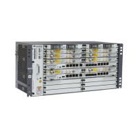
Details internal components of the OMB cabinet with AC power supply.
Details internal components of the OMB cabinet with DC power supply.
Specifies recommended clearances around the OMB cabinet for installation.
Specifies minimum clearances around the OMB cabinet for installation.
Illustrates the procedure for mounting the OMB cabinet on a pole.
Illustrates the procedure for mounting the OMB cabinet on a wall.
Details steps for wall mounting the OMB cabinet, including drilling and bolt installation.
Details steps for pole mounting the OMB cabinet, including bracket and backplane installation.
Shows the installation of RTN 905 within an OMB cabinet for AC power.
Shows the installation of RTN 905 within an OMB cabinet for DC power.
Describes the correct orientation and placement for installing the RTN 905 unit.
Details the installation procedure for the SLPU module relative to the RTN 905.
Covers the installation and routing of protective ground (PGND) cables for cabinets and RTN 905.
Explains how to connect the AC input power cable to the OMB cabinet.
Details connecting the input power cable to the RTN 905 equipment.
Describes connecting the DC input power cable to the OMB cabinet's distribution box.
Details connecting the DC input power cable to the RTN 905's distribution box.
Shows how to install E1 interface cables for data transmission.
Illustrates the process of installing Ethernet network cables.
Describes the installation of Intermediate Frequency (IF) cables.
Details the procedure for installing fiber optic cables.
Explains connecting signal monitoring cables via the MON port.
Verifies that the cabinet is correctly installed according to design and securely fixed.
Ensures the installation area is clean and free from debris or excess materials.
Provides diagrams and codes for routing various cables through cabinet holes.
| Brand | Huawei |
|---|---|
| Model | OptiX RTN 905 |
| Category | Microphone system |
| Language | English |