2012 series Tooling (HK969) Alcoa Fastening Systems
13
Equipment Required:
• Shop airline with 90 - 100 psi max.
• Air regulator
• Fill Bottle 120337 (supplied with tool).
• Large flat blade screwdriver
• Nose assembly or optional Stall Nut
• Fasteners (optional)
• Optional Stall Nut, part no. 124090. (Stall nut is
used to load tool during bleeding and for meas-
uring stroke.)
Preparation:
1. Install air regulator in
air line and set pres-
sure to 20-40 psi.
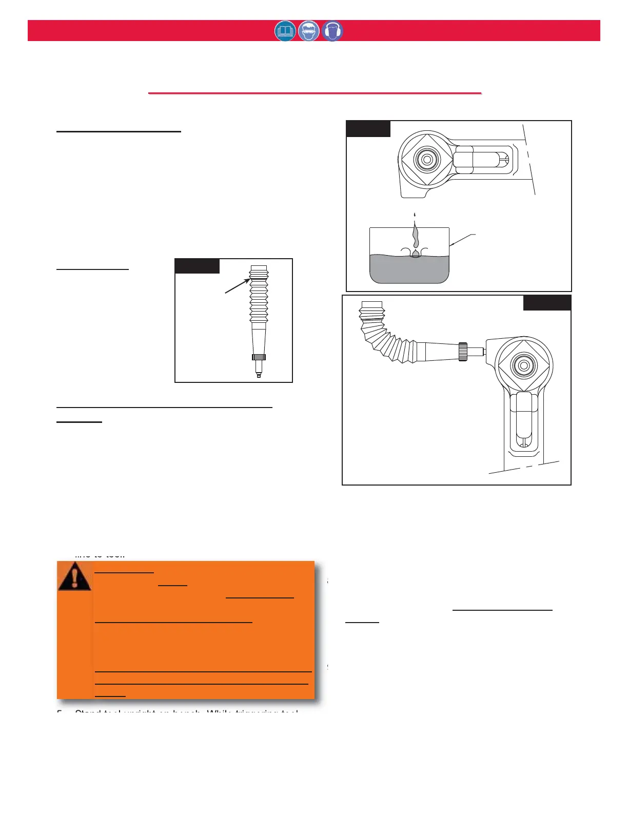
2. Fill bleed bottle
almost full of
DEXRON III ATF
(automatic transmis-
sion fluid). Figure 4
.
Procedure to Fill Empty Tool (new or
rebuilt):
1. Attach the tool air source momentarily to seat air
piston at bottom of cylinder and disconnect tool.
With fill port facing up, lay tool on its side.
2. With a screwdriver, remove bleed plug from fill
port.
3. Screw fill bottle into fill port in the head.
4. Set air line pressure to 20-40 psi and connect air
line to tool.
5. Stand tool upright on bench. While triggering tool
slowly (20-30 cycles), bend fill bottle at right
angles to tool. Figure 4.2. Air bubbles will
emerge from tool. When bubbles stop, cycling
may be discontinued.
6. When trigger is released, pull piston returns to
idle position (full forward). Disconnect tool from
air line.
7. Lay tool on its side. Remove fill bottle. Top off
fluid in fill port. Install bleed plug and tighten.
8. Connect air line to tool. There is a choice of two
procedures for measuring the stroke: with and
without a stall nut. See S
EE HOW TO MEASURE
STROKE section and follow the selected proce-
dure. If stroke is less than specified, remove
bleed plug and top off fluid. Reinstall bleed plug.
9. Increase air pressure to specification. Install two
fasteners to check function and installation in a
single stroke, or cycle tool with stall-nut fully
threaded onto piston to load up tool. Measure
stroke again. Remove plug and top off fluid.
Reinstall plug and cycle again. Measure again.
Continue this process until stroke meets mini-
mum requirements.
continued
Fig. 4
Fig. 4.1
Fig. 4.2
WARNING
Air pressure MUST be set to 20-40 psi to
prevent possible injurious high pressure
spray.
NEVER CYCLE TOOL WITHOUT:
BLEED PLUG TIGHTENED
FILL BOTTLE TIGHTENED IN TOOL, or
FILLPORT HELD OVER A RECEPTACLE Figure 4.1
When not properly contained any fluid pres-
ent in tool will spray out. Severe injury may
result.
F
F
ILLING
ILLING
AND
AND
B
B
LEEDING
LEEDING
P
P
ROCEDURE
ROCEDURE