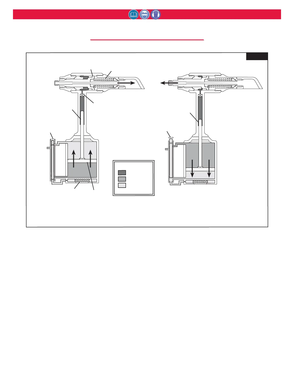
Fig. 2
When the tool is connected to the air supply, air
pressure holds the Throttle Valve in the UP
position, and air pressure is directed to the top of
the Air Piston keeping it down.
When the trigger is depressed, the Throttle
Valve moves to the DOWN position, and pres-
surized air is directed to the bottom of the Air
Piston, causing the it to move upward (Fig.2a).
The air above the piston is exhausted and direct-
ed through the center of the Throttle Valve and
out the bottom of the tool through the Muffler.
As the Hydraulic Piston Rod moves upward, a
column of fluid is forced into the tool head,
which moves the PULL Piston rearward. The
attached nose assembly moves with the PULL
Piston to start fastener installation.
When fastener installation is completed, and
upon trigger release, air pressure with the assis-
tance of a spring causes the Throttle Valve to
return to its UP position.
Pressurized air is re-directed to the top of the
Air Piston (Fig.2b), causing the Air Piston and
Hydraulic Piston Rod to move downward. The
air from below the piston is exhausted through
the Muffler at the bottom of the tool.
As the Hydraulic Piston Rod moves downward
and hydraulic pressure is released from the
PULL Piston, a Spring behind the PULL
Piston returns it to its forward position. The
Damper Valve impedes oil flow at pinbreak
helping prevent “Tool Kick”.
Fig. 2a
Fig. 2b