2012 series Tooling (HK969) Alcoa Fastening Systems
16
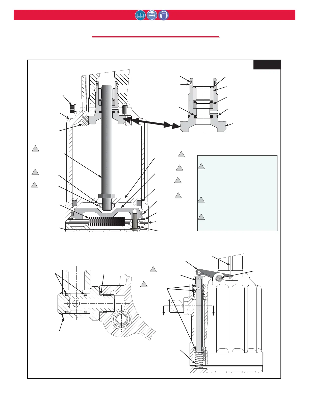
Pivot
Screw
123754-1
Throttle Arm
125467-2
Throttle Valve
507396
O-Ring
(3)
116272
Spring
Throttle
Cable
A
A
116134-1 Gland Assembly
Notes:
Piston and Rod Assy 123777-3 includes:
123776-2 Piston Assy (including:)
123753-1 Air Piston
501451 Quad-Ring
111803-1 Piston Rod
506493 Washer
505420 Self-locking Nut
Cylinder Head Assy 123778-1 includes:
111959-2 Cylinder Head (not sold separately)
500864 O-Ring
Throttle Valve Assy 125472-2 includes:
125467-2 Throttle Valve (not sold separately)
507396 O-Ring (qty. 3)
2
3
1
1
1
1
1
1
2
2
3
3
Section A-A
500778
O-ring
500779
O-ring
(2)
507164
Swivel
Assembly
123753-1
Air Piston
111959-2
Cylinder
Head
506493
Washer
505420
Locknut
115554-2
Muffler
128791
Bottom
Plate
504127
Screw
(3)
506878
Retaining Ring
500864
O-Ring
501451
QUAD Ring
126941 Gasket
125118
Pivot
Screw
111803-1
Piston Rod
125471
Cylinder
Assy
116408
Bumper
125139 Gland
Housing
500786 O-ring
506566 Polyseal
123906 Spacer
506565
Retaining Ring
500784
O-ring
501090
Back-up
Ring
501414
QUAD-Ring
Figure 7
*
* When replacing Cylinder Assembly Stickers (590350, 590351,
and 590347) MUST be ordered and placed in the location shown
in Figure 15.
T
T
OOL
OOL
A
A
SSEMBLY
SSEMBLY
D
D
RAWINGS
RAWINGS
(pages 16-22)