11
202 Series Tooling (HK938) Alcoa Fastening Systems
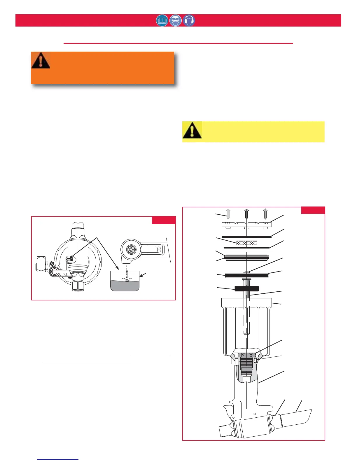
For component identification, refer to Figures 14 & 15
and Parts Lists on pages 20 & 21.
NOTE: The following procedure is for complete
disassembly of tool. Disassemble only
components necessary to replace damaged O-
rings, Quad rings, Back-up rings, and worn or
damaged components. Always use soft jaw vice to
avoid damage to tool.
1. Disconnect tool from air source.
2. Unscrew Retaining Nut (7) and remove nose
assembly.
3. Unscrew Bleed Plug (55), from top of
Handle/head. Turn tool over and allow fluid to
drain into container (Fig. 1). Discard fluid.
4. 202 & 202L: Pull Pintail Deflector (24) off of End
Cap (21). (Figure 2)
202B: By reaching through the window of Pintail
Bottle (24) remove Retaining Ring (62) and
Washer (63), then remove Pintail Bottle (24) and
Adapter (64). (Figure 5).
202V & 202LV: Please reference Disassembly of
Pintail Bottle and Vacuum System Procedure.
5. Remove Throttle Arm Pivot Screw (48) and Lever
Guard (73), and lift out Throttle Arm (53).
Disconnect ball end of Cable Assembly (2) from
Throttle Arm.
6. Hold tool in vise with bottom up. (Fig. 2) Remove
Button Head Screws (40) with 1/8 hex key.
Remove End Cap (41) and Gasket (39). Remove
Muffler (42) from end cap. Remove Spring (49)
from Throttle Valve (Fig.14).
7. Tap Cylinder Head (45) down with soft mallet (to
take pressure off ring), and remove Retaining Ring
(38) (Fig.2).
8. Screw Button Head Screws (40) back into
Cylinder Head. Carefully pry on screws to remove
head. Remove O-ring (46).
9. To remove air piston from cylinder, pull on Lock
Nut (43) with vise grips. Remove Quad Ring (47).
10. Remove Bumper (34) from Gland Assembly.
Unscrew Gland Assembly (25) with 1 3/8 socket
wrench and extension bar.
11. First remove Retaining Ring (30) from Gland (26).
Pull out Spacer (29) and Polyseal (28). Then
remove O-rings (31 & 27), Quad Ring (33), &
Back-up Ring (32) (Fig. 14).
drain hydraulic fluid.