12
2024 Series Tooling Alcoa Fastening Systems
Head/handle 2024, 2024L
(Refer to Figures (7, 8 & 14)
NOTE:
Clean components with mineral spirits, or similar solvent;
inspect for wear/damage and replace as necessary.
Replace all seals of disassembled components. Use O-
rings, QUAD rings and Back-up rings in Service Parts
Kit, P/N 2024KIT or 2024VKIT Smear LUBRIPLATE
130AA or PARKER-O-LUBE on O-rings, QUAD rings,
Back-up rings and mating parts to ease assembly.
Assemble tool taking care not to damage O-rings, QUAD
rings, or Back-up rings.
1. If removed, position Cable Assembly (2) in Trigger
(5) slot and slide Dowel Pin (3) through holes in
trigger and cable assembly. Position assembled
trigger in handle and drive Pin (4) through holes in
handle and trigger (Fig. 14).
2. Screw Nose Adapter (8) into Head (1) and tighten.
3. Thread POLYSEAL Insertion/removal Tool (121694-
2024) into head.
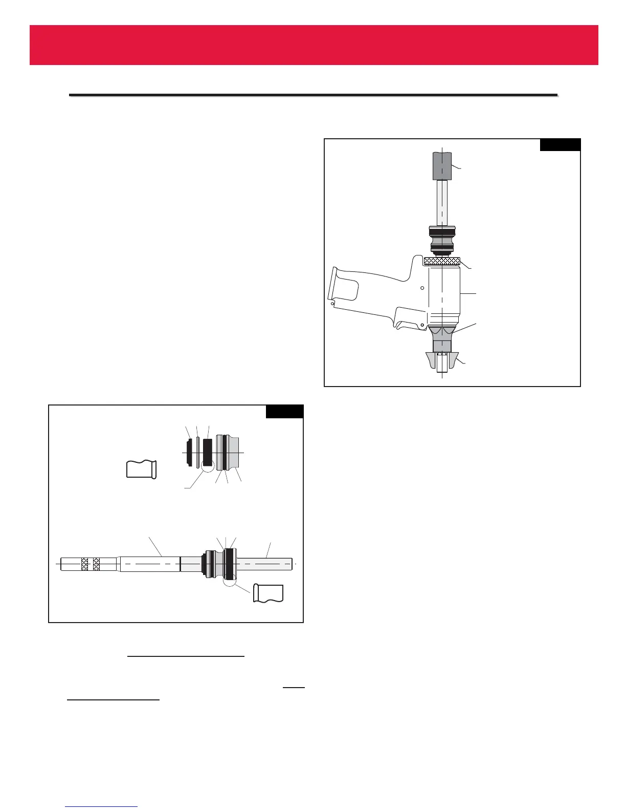
4. Assemble piston (6), Polyseal (18) and retaining ring
(16) (Fig 7). Note Polyseal orientation.
5. Assemble front gland (15), O-ring (12), Back-up ring
(11), Polyseal (14) and Gland Cap (10). Note
Polyseal orientation.
6. Thread Piston Assembly Tool (123111-2 for 2024, &
2024V) or (123111-4 for 2024L, & 2024LV) onto
Piston (6). Slide complete Gland Assembly and
Wiper Seal (9) onto Piston (6).
7. Install assembled components in gently from rear of
tool using a press as shown in (Fig. 8).
8. Remove Piston Assembly Tool (123111-2 or 123111-
4) and POLYSEAL Insertion / removal (121694-
2024) Tool.
9. Install Rear Wiper Seal (23) into End Cap (21) (Fig.
14).
10. Slide Spacer (22) and Spring (19) into End Cap (21)
and then thread End Cap assembly into rear of
Head. NOTE: For 2024V please reference
Assembly of Pintail Bottle and Vacuum System
procedure. (Refer to Figures 5, 6 & 10)
General:
(Refer to Figures 2 & 9)
11. Hold Head/Handle (1) inverted in vice (with soft
jaws). Place inverted Cylinder Assembly (35) on
base of handle. Timing pin maintains orientation.
12. Assemble Gland assembly (25) with new seals (Fig.
9). Note orientation of polyseal. Apply Anti-Seize
Compound (Huck P/N 508183) to threads of Gland
Assembly. Screw gland into head/handle and Torque
to 50 ft. lbs. using 1 3/8 socket wrench.
13. Push Bumper (34) firmly over gland. NOTE: The
side of the bumper with two slots must face
toward the bottom of the tool.
A
A
SSEMBLY
SSEMBLY
I
I
NSTRUCTIONS
NSTRUCTIONS
2024
2024
ALL
ALL
MODELS
MODELS