10
2025 Series Pneudraulic Installation Tools (HK1006) Alcoa Fastening Systems & Rings
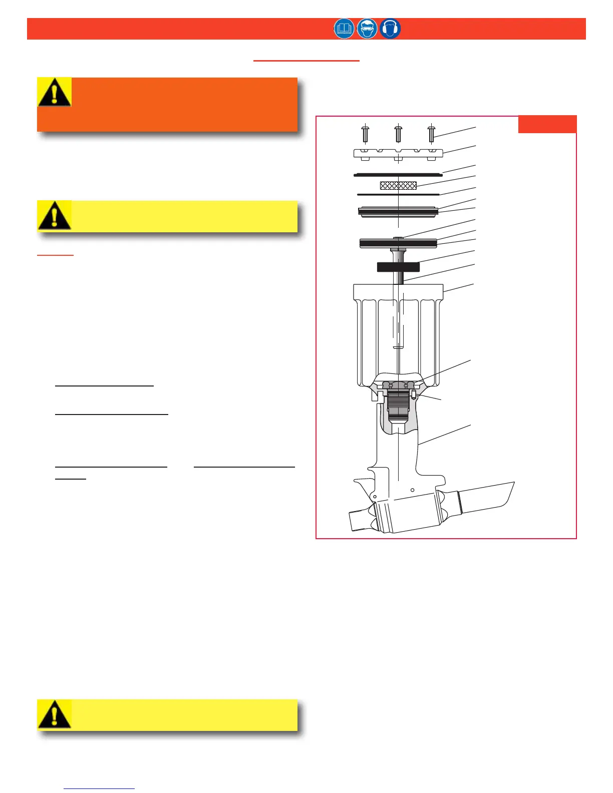
DIsasseMbly
WARNING: Disconnect the air hose from the
tool before performing any maintenance.
Serious personal injury could result if the air
hose is connected.
This procedure is for complete disassembly of the tool.
Disassemble only those components necessary to replace
damaged O-rings, Quad-rings, Back-up rings, and worn or
damaged components. For component identication, see
Figures 2, 14, & 15.
CAUTION: Always use a soft-jaw vise to avoid
damaging the tool.
general
NOTE: For models 2025S & 2025SL, follow the
procedures for models 2025 & 2025L.
1. Disconnect the tool from the air source.
2. Unscrew the retaining nut (7), and remove the nose
assembly.
3. Unscrew the bleed plug (55) from top of the handle/
head. Turn over the tool and drain the uid into a
container. (Figures 10 & 14)
4. Models 2025 & 2025L: Pull the pintail deector (24)
off the end cap (21).
Models 2025B & 2025LB: Reach in the window of the
pintail bottle (24) and remove the retaining ring (62)
and washer (63); then remove the pintail bottle (24)
and adapter (64). (Figures 14 & 15)
Models 2025V & 2025LV: See PIntaIl bottle/VacuuM
systeM on page 11.
5. Remove the throttle arm pivot screw (48) and the
lever guard (73). Lift out the throttle arm (53), and
disconnect ball end of the cable assembly (2) from it.
6. Secure the tool in a vise, upside-down. (Figure 2)
Remove the button head screws (40) with 1/8” hex
key. Remove the end cap (41) and gasket (39), and
remove the mufer (42) from the end cap. Remove
the spring (49) from the throttle valve. (Figure 14)
7. Tap down the cylinder head (45) with a soft mallet (to
take pressure off the ring), and remove the retaining
ring (38). (Figure 2)
8. Screw the button head screws (40) into the cylinder
head, and carefully pry on the screws to remove the
head. Remove the O-ring (46).
9. Pull on lock nut (43) with vise-grips to remove air
piston from cylinder. Remove piston Quad-ring (47).
CAUTION: Take care to not scratch the piston
rod or cylinder when removing.
10. Remove the bumper (34) from the gland assembly.
Unscrew gland assembly (25) with 1-3/8” socket
wrench and extension.
11. Remove the Spirolox
®
Retaining Ring (30) from the
gland (26), and then pull out the spacer (29) and
Polyseal (28). Remove the O-rings (31 & 27), Quad-
ring (33), and Back-up ring (32). (Figure 14)
12. Lift the cylinder (35) from the handle/head (1).
13. Turn over the tool (1) and drain the uid into a
container; discard the uid.
14. Remove the throttle valve (52) from the air cylinder
(35), and remove the O-rings (50). (Figure 14)
Spirolox is a registered trademark of Smalley Steel Ring Company
fIgure 2