11
2025 Series Pneudraulic Installation Tools (HK1006) Alcoa Fastening Systems & Rings
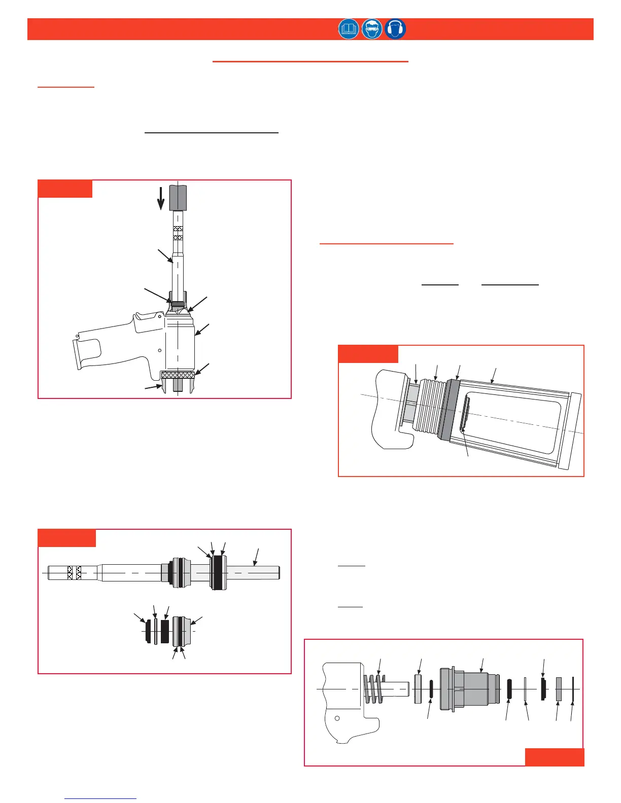
head/handle
This procedure is applicable to models 2025 and 2025L.
For component identication, see Figures 3, 4, & 14.
NOTE: For 2025V, see PIntaIl bottle/VacuuM systeM on
page 11.
1. Unscrew end cap (21); remove spring (19), spacer
(22), and wiper seal (23).
2. Thread the Polyseal Insertion Tool into the rear of the
handle/head. (Figure 3)
3. Slide the spacer (P/N 123112-2 [2025] / 123112-3
[2025L]) onto the piston. Thread the Piston Assembly
Tool (P/N 123111-2 [2025] / 123111-4 [2025L]) onto
the piston.
4. Push the piston and front gland assemblies out the
back of the handle/head (1). Allow clearance, with
stand-off, as the piston leaves the tool. (Figure 4)
5. Un-thread the Piston Assembly Tool and remove
Spacer from the piston. Re-thread the Piston
Assembly Tool onto the piston, then slide the front
gland assembly off the piston (6). (Figure 4)
6. Remove the Piston Assembly Tool from the piston (6),
and remove the Polyseal Insertion Tool from the rear
of the head/handle (1).
7. Remove the retaining ring (16), washer (17), and
Polyseal (18) from the piston.
NOTE: Inspect the hydraulic piston for wear, scoring,
and damage; replace if necessary.
8. Unscrew the adapter (8). (Figure 14) Inspect all seals
and parts.
9. If trigger cable assembly (2) is damaged, remove it by
driving the pin (4) out with punch. Remove dowel pin
(3) to disconnect cable from trigger.
PIntaIl bottle/VacuuM systeM
This procedure is applicable to models 2025V and
2025LV only; it should be used in conjunction with
the previous sections, general and head/handle. For
component identication, see Figures 5, 6, & 15.
1. Reach through the window of pintail bottle (24) and
remove the retaining ring (62) and washer (63).
(Figure 5)
2. Remove the pintail bottle (24), and then disconnect
the tube from the connector (54). (Figure 15)
3. Remove the adapter (64) and tube/slide assy (70).
4. Remove the end cap (21) and spring (19). (Figure 6)
5. Remove the spacer (22) and O-ring (68) from the
spring side of the end cap.
6. Remove the retaining ring (66), wiper housing (67),
wiper seal (23), washer (71) and O-ring (69) from the
bottle side of the end cap.
7. Remove the O-rings (65) from inside the adapter and
tube/slide assembly (70). (Figure 15)
fIgure 4
fIgure 3
DIsasseMbly (ContInueD)
fIgure 5
fIgure 6