8
2025 Series Pneudraulic Installation Tools (HK1006) Alcoa Fastening Systems & Rings
The 2025 series of tools ship with a plug in the air inlet
connector. The connector has 1/4-18 female pipe threads
to accept the air hose tting. Huck recommends quick-
disconnect ttings and a 1/4” inside-diameter air hose.
The air supply should be equipped with a lter-regulator-
lubricator unit, and access to a 90 psi (6.2 BAR) air
supply capable of 20 ft³/s (.57 m³/s).
NOTE: Air quick-disconnect ttings and air hoses are not
available from Huck International, Inc.
1. Remove the shipping plug from air inlet connector
and add a few drops of an approved hydraulic uid.
2. Screw the quick-disconnect tting into the air inlet
connector.
3. Set the air pressure on the regulator to 90–100 psi,
and connect the air hose to the tool.
4. Press and release the trigger a few times to cycle
the tool. Disconnect the air hose from the tool, and
remove the retaining nut.
5. Select the proper nose assembly for the fastener
being installed.
6. Screw the collet assembly (including the lock collar
and shim if applicable) onto the spindle and tighten
with a wrench.
7. Slide the anvil over the collet assembly and into the
counterbore. Slide the retaining nut over the anvil,
and screw the nut onto the head.
8. Connect the air hose to the tool and install fasteners
in a test plate of proper thickness with proper size
holes. Inspect the fasteners.
If fasteners do not pass inspection, see
troubleshootIng to investigate possible causes.
NOTE: On older nose assemblies with lock collars, use
Loctite
®
243™ on collet threads, because the 2025 pull
piston does not have staking holes. Refer to the nose
assembly drawings that shipped with nose assemblies.
Teon is a registered trademark of du Pont de Nemours and Company.
Threadmate is a registered trademark of Parker Intangibles, LLC.
Loctite is a registered trademark of Henkel Corporation, U.S.A.
preparatIon for use
CAUTION: Do not use Teon
®
tape on
pipe threads. Tape can shred, resulting in
malfunctions. Threadmate
®
is available in a
4oz. tube from Huck (P/N 508517).
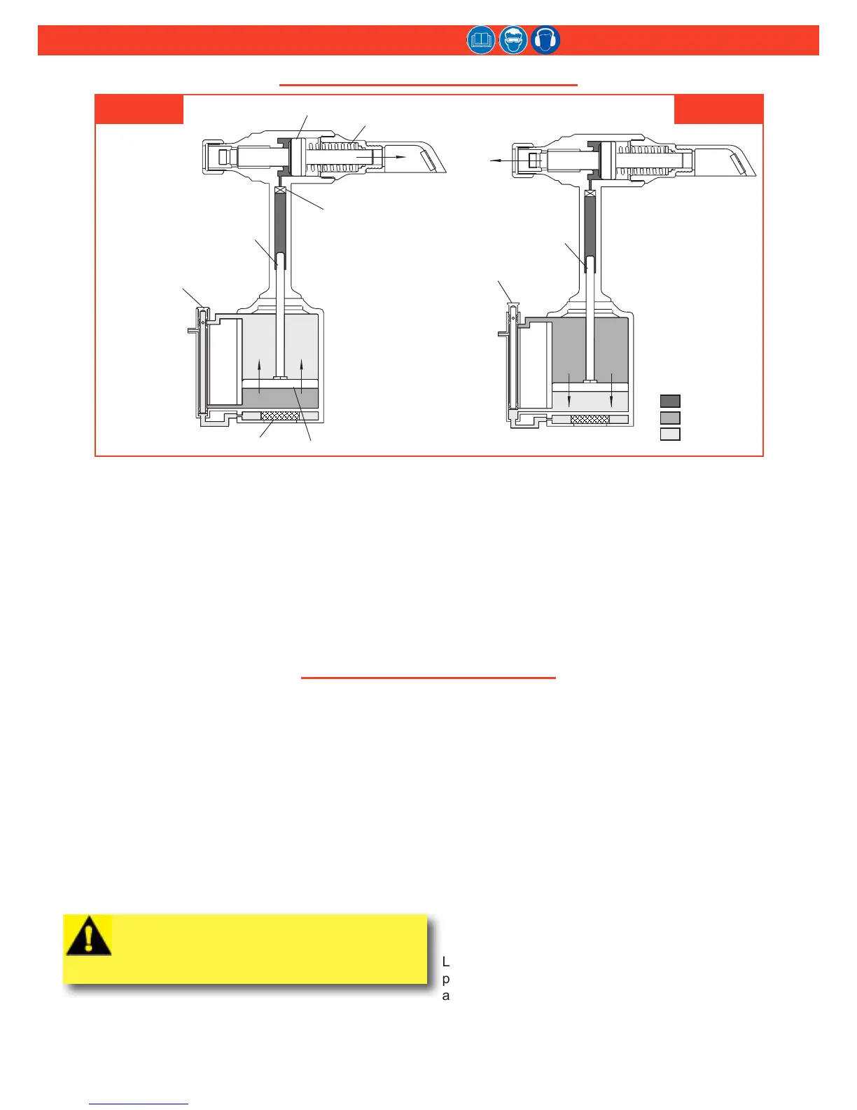
When the trigger is pressed, the throttle valve moves
downward to the PULL position, and pressurized air
is directed to the bottom of the air piston, causing it to
move upward (Figure 1A). The air above the air piston is
exhausted and directed through the center of the throttle
valve and out the bottom of the tool.
As the hydraulic rod moves upward, a column of uid is
forced into head, which moves the pull piston backward.
The attached nose assembly moves with the pull piston
to start fastener installation.
When fastener installation is completed, the trigger is
released. Air pressure, with the assistance of a spring,
sends the throttle valve to the up (RETURN) position.
Pressurized air is re-directed to the top of the air piston
(Figure 1B), causing the air piston and hydraulic rod to
move downward.
The air from below the piston is exhausted through the
bottom of the tool, and springs force the pull piston to
return to its home position. The damper valve (Figure 1A)
impedes oil ow at pinbreak to prevent “tool kick.”
fIgure 1a fIgure 1b
prInCIples of operatIon