14
2025 Series Pneudraulic Installation Tools (HK1006) Alcoa Fastening Systems & Rings
fIll anD bleeD
This section documents the “bleed-&-ll” procedure. For
component identication, see Figures 9, 10, & 11.
requIred equIPMent
• Automatic Transmission Fluid (ATF) DEXRON III or
equivalent (Refer to the sPecIfIcatIons sections for
more information.)
• Shop air-line with 90–100 psi (6.2–6.9 BAR) max.
• Air regulator
• Fill and Bleed Bottle (P/N 120337, supplied with tool)
• Large at-blade screwdriver
• Stall Nut (P/N 124090 or 125340, optional)
• Nose assembly
• Fasteners (optional)
PreParatIon
• Install air regulator
in the air-line and
set the pressure to
20–40 psi (1.4–2.8
BAR).
• Add an approved
hydraulic uid to the
ll point of the Fill
and Bleed bottle.
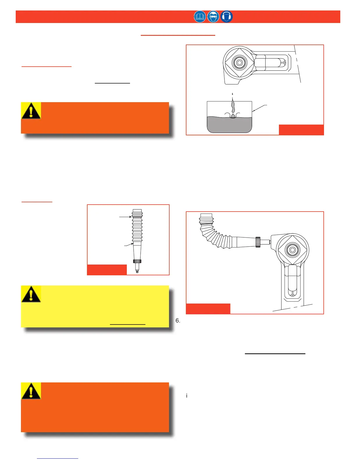
To bleed and ll the tool:
1. Lay the tool on its side with the ll port facing up,
and remove the bleed plug (55) from the ll port.
2. Connect the tool to shop air-line. If uid is present,
hold the tool over a suitable container with ll port
facing into container. Cycle the tool several times to
drain old uid, air, and foam. (Figure 10)
3. Screw the ll bottle into the ll port.
4. Stand the tool upright on a bench. Trigger the tool
slowly (20–30 cycles), and bend the ll bottle at a
right-angle to the tool. (Figure 11)
When air bubbles stop accumulating at top of the
bottle, stop cycling the tool. When the trigger is
released, the pull piston returns to the idle position
(full-forward).
5. Disconnect the tool from the air-line.
6. Lay the tool on its side and remove the ll bottle.
Top off the uid in the ll port, and install and tighten
the bleed plug.
7. Connect the air-line to the tool and measure the
stroke as described in MeasurIng tool stroke on
page 15. If the stroke is less than specied,
remove the bleed plug and add uid. Re-insert the
bleed plug and recheck the stroke.
8. Increase the air pressure to specications. Install
two fasteners to check the function and installation
in a single stroke, or cycle the tool with a stall nut
fully threaded onto the piston to load up the tool.
Measure the stroke again. Remove the plug and
add uid. Re-insert the plug and cycle and measure
again. Repeat this process until the stroke meets the
minimum requirements.
WARNING: Avoid contact with hydraulic
uid. Hydraulic uid must be disposed of
in accordance with local regulations. See
MSDS for hydraulic uid shipped with tool.
Figure 9
WARNING: Air pressure must be set at
20–40 psi (1.4–2.8 BAR) to prevent possible
injury from high-pressure spray.
If the bleed plug (55) is removed, the Fill and
Bleed bottle must be in place before cycling
the tool.
Figure 10
CAUTION: All uid must be purged from the
tool before relling. The tool stroke will be
diminished if the uid is aerated.
For optimal performance, rell with a uid
that is recommended in sPecIfIcatIons.
Figure 11