18
2025 Series Pneudraulic Installation Tools (HK1006) Alcoa Fastening Systems & Rings
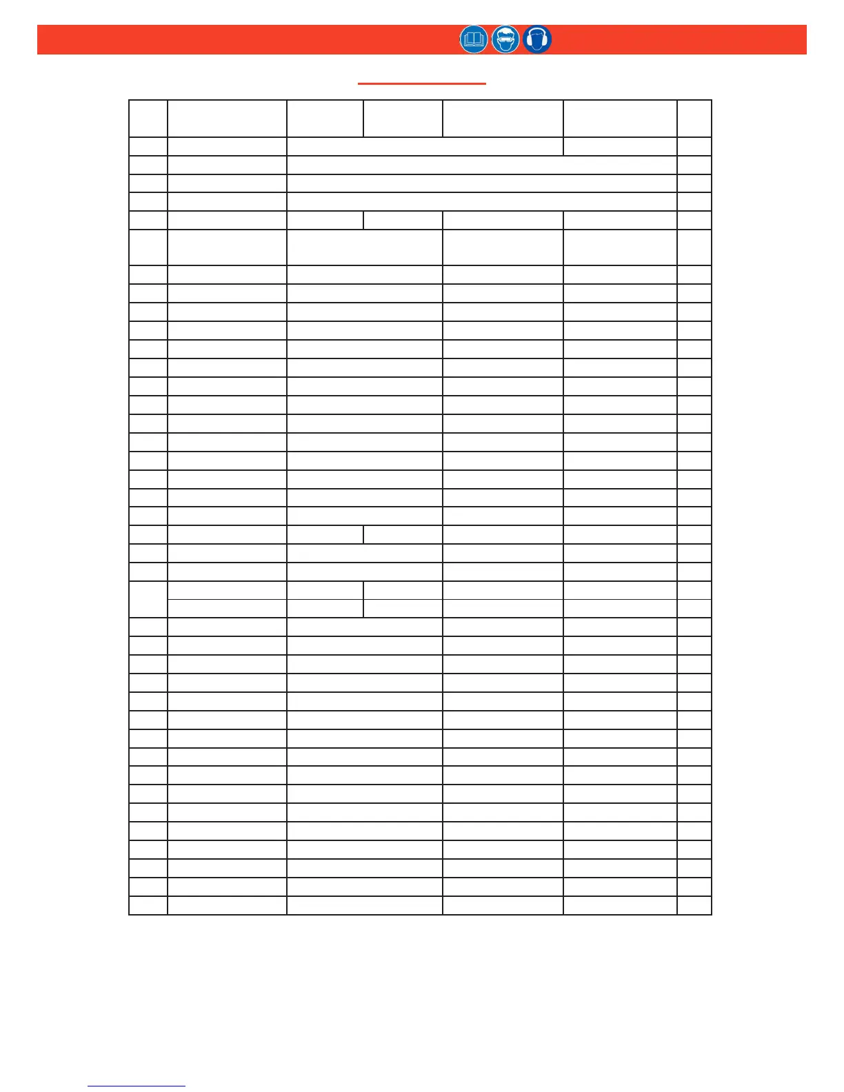
parts lIst
ITEM Description
2025
2025L
2025B
2025LB
2025V
2025LV
2025S
2025SL
QTY
1** Handle Assy 125736 126980 1
2 Cable Assy 116404-1 1
3 Dowel Pin 505496 1
4 Pin 500621 1
5 Trigger 124333-2 124333-1 124333-2 124333-2 1
6
Piston Assy (includes
Items 16, 17, & 18)
125738 (2025, 2025B)
125738-1 (2025L, 2025LB)
125738-2 (2025V)
125738-3 (2025LV)
125738 (2025S)
125738-1 (2025SL)
1
7 Retaining Nut 111795 111795 111795 1
8 Adapter 123761 123761 123761 1
9 Wiper Seal 505817 505817 505817 1
10 Gland Cap 122432 122432 122432 1
11 Back-up Ring 501110 501110 501110 1
12 O-Ring 500816 500816 500816 1
13 O-Ring 500778 500778 500778 1
14 Polyseal 505818 505818 505818 1
15 Front Gland 123757 123757 123757 1
16 Retaining Ring 502833 502833 502833 1
17 Washer 507448 507448 507448 1
18 Polyseal 507400 507400 507400 1
19 Compression Spring 507446 507446 507446 1
20** WARNING Sticker 590240-1 590240-1 590240-1 1
21 End Cap 125739 127030 125863 125739 1
22 Washer 507323 507323 507323 1
23 Wiper Seal 507351 507351 507351 1
24
Pintail Deector 124210 n/a n/a 124210 1
Pintail Bottle n/a 123772 123772 n/a 1
25 Gland Assy 125742 125742 125742 1
26 Gland Housing 125740 125740 125740 1
27 O-Ring 500787 500787 500787 1
28 Polyseal 507447 507447 507447 1
29 Spacer 125741 125741 125741 1
30 Retaining Ring 506876 506876 506876 1
31 O-Ring 500785 500785 500785 1
32 Back-up Ring 501091 501091 501091 1
33 QUAD Ring 501075 501075 501075 1
34 Bumper 116408 116408 116408 1
35* Cylinder Assy 125733 125733 125733 1
36 Piston Rod 125743 125743 125743 1
37 Air Piston 130729 130729 130729 1
38 Retaining Ring 507445 507445 507445 1
39 Gasket 126941-4 126941-4 126941-4 1
40 Screw 504127 504127 504127 3
(continued on next page)
* When replacing Cylinder Assembly (35), Stickers (59, 60, & 61) MUST be ordered and placed in the
location shown in Figure 14.
** When replacing Handle Assembly (1), WARNING Sticker (20) MUST be ordered and placed in the
location shown in Figure 14.