12
244 series Pneudraulic Installation Tools (HK989) Alcoa Fastening Systems & Rings
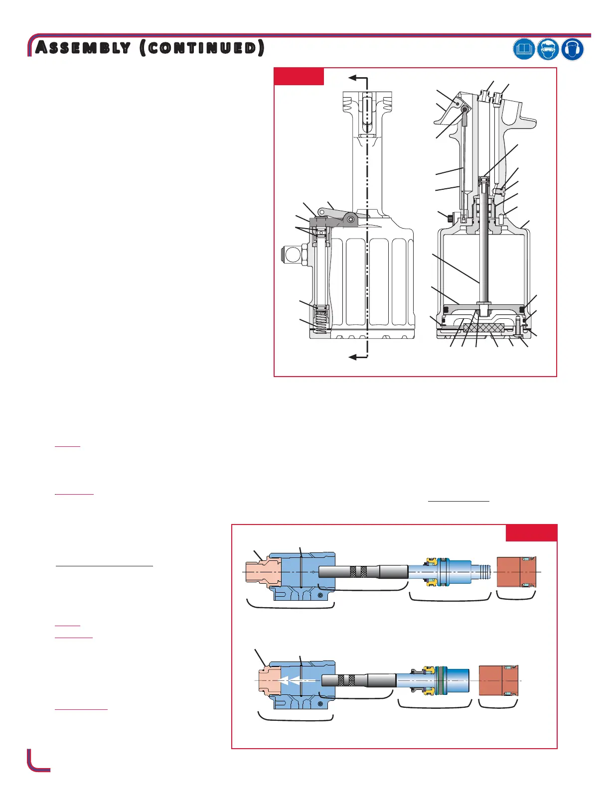
11. Install Swivel Assembly (86) in Cylinder Assembly
(51), and reattach air hose (if removed). (Fig. 9a/b)
12. If Seat Assembly (80) is being replaced, push seat
and seal assembly in using soft drift. Take care not
to damage ball seat surface. (Fig. 9)
13. Assemble hydraulic Piston (18) with new seals
(16,17). Lubricate with LUBRIPLATE or PARKER
SUPER-O-LUBE. (Fig. 9a/b)
14. Install Nose Adapter (9) on front of head. Apply
Loctite® 243™ threadlocker to threads per
manufacturer’s instructions. Torque to 50-60
ft. lbs. (Fig. 7) Loctite is a registered trademark of Henkel
Corporation.
15. Install internal Cylinder Head O-ring.
16. Place seals on rear gland/sleeve
17. Thread Piston Assembly Tool onto Pull Piston. Using
an arbor press, press Cylinder sleeve over the back
of the piston until seated on piston. Slide complete
Front Gland Assembly and other components, as
shown in Fig.7, over Piston Assembly Tool onto
Piston.
18. Press entire piston, gland assembly, and components
into head. Remove Piston Assembly Tool from piston.
19. 244X: (Fig. 9a) Place Seals (20) and (24) on Rear Gland
(19). Push complete assembly into head and screw in
End Cap (21), and torque to 50 - 60 ft. lbs.
244OSX: (Fig. 9b) Place seals (20 & 24) on Rear Gland
(19). Push complete assembly into head and screw
in End Cap (21), torque to 50-60 ft. lbs. Thread Stop
(89) into End Cap two turns. Thread
Locknut (92) onto Piston Stop (89) and
leave loose. For adjustment, refer to
Measuring Tool sTroke section of this
manual (Page 20).
20. Install Quad-Ring (72) and Spacer. Slide
Reservoir Plunger (73) in.
244X: Install two Springs (71)
244OSX: Install Spring (93) rst, then
Spring (71).
21. Screw Housing/Spacer Assembly into
head. (Fig. 1)
22. 244X ONLY: (Fig. 1 & 9a/b)
Push Pintail Deector (22) onto rear of
Piston (18).
22. Place O-ring (39) on Plug (40) and screw assembly into
Handle (1). (Fig. 6)
23. Install Pull (29) and Return (25) Gland Assemblies in
handle. Push head down on glands. Place tool in a vise
Head down and install 4 Screws (69) and torque to 170
inch pounds. (Fig. 6 & 9a/b))
24. Tool is now completely assembled except for relief
and check valves. See Fill and Bleed procedure for
replacement of valve components.
Cylinder Head
Cylinder Head
Piston
Assembly Tool
Assembled
Pull Piston and
Front Gland
Piston Assembly
Tool
Assembled
Pull Piston and
Front Gland
Internal Cylinder
Head O-Ring
Assembled
Cylinder Sleeve
Assembled
Cylinder Sleeve
Internal Cylinder
Head O-Ring
FIG. 7
FIG. 6
 Loading...


