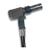
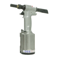
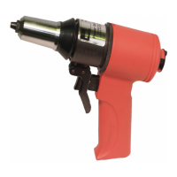
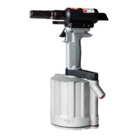
244 series Pneudraulic Installation Tools (HK989)Alcoa Fastening Systems & Rings
11
Clean components with mineral spirits or similar solvent.
inspect for wear or damage and replace as necessary.
Replace all seals of disassembled components, using the
O-rings, Quad-Rings and Back-up rings provided in Service
Kit 244KIT. Smear LUBRIPLATE 130AA on O-rings, Quad-
Rings, Back-up rings and mating parts to ease assembly.
Assemble tool without damaging seals.
LUBRIPLATE is a registered trademark of LUBRIPLATE Lubricants Company.
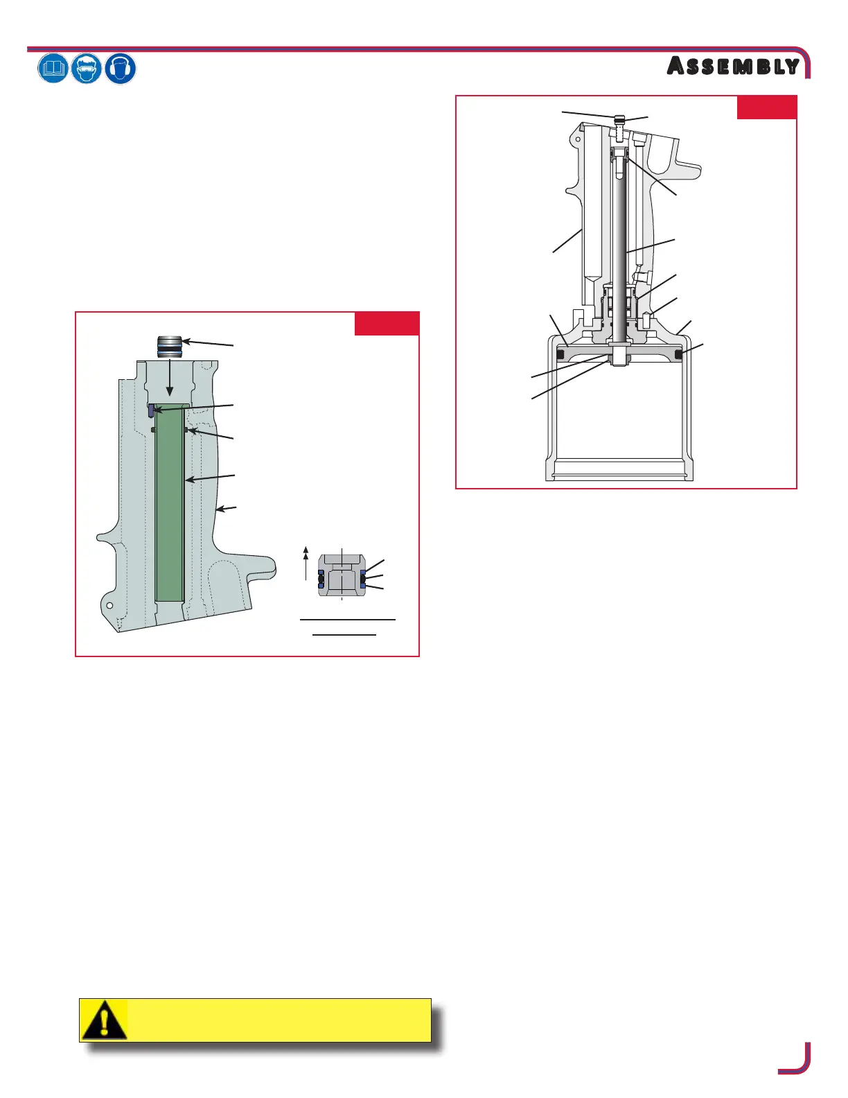
1. Install internal handle O-ring. Holding handle inverted in
a vice, Install internal timing pin. Align small slot in sleeve
with timing pin in handle and press in until seated. (Fig.
4)
2. With handle still inverted in a vice, install Intensier
Piston (37), with O-ring (35) and Back-up rings (36) in
place into handle. (Fig. 4)
NOTE: The Intensier piston must be pressed in from
bottom of handle to avoid damaging seals.
NOTE: Ensure intensier piston is correctly oriented
prior to installation, as shown in Fig. 4.
3. Place Cylinder Assembly (51) on handle with Timing
Pin (50) positioned in matching hole. Assemble Gland
Assembly (41) (Fig. 9a/b). Screw complete Gland
assembly into handle. Torque to 75-80 ft. lbs. using a 1
3/8 socket wrench. (Fig 5)
4. Push Piston Rod (63) through Air Piston (61) from at
side. Drop Washer (59) over thread and screw Locknut
(58) onto rod. Using 9/16 wrench and socket, hold rod
hex and torque nut using 9/16 socket to 28-32 ft. lbs.
(Fig 5).
5. Push assembled Air Piston and Rod into Air Cylinder and
Gland Assembly (41) until it stops. Apply Loctite® 243™
to threads of Screw (34), and press Screw, with O-ring
(38) in place through hydraulic Piston Assembly (33), and
screw into top of piston rod. Hold Locknut (58) with 9/16
socket and extension and torque Screw (34) using 7/64
hex key to 55-60 in. lbs.
Loctite is a registered trademark of Henkel Corporation.
6. Push Cylinder Head (60) with O-ring (53) in place squarely
into Cylinder. Install Retaining Ring (62). (Fig. 6)
7. Hold handle upside down in vise. Position Muer (57)
on center of Cylinder Head (60), Place Gasket (54) on
Cylinder Assembly (51), place Bottom Plate (56) on top of
Gasket and secure with 3 Button Head Screws (55) using
1/8 hex key. (Fig. 6)
8. Turn tool upright. Drop Spring (65) into Throttle Valve
hole in Cylinder. Push Throttle Valve (67) with O-rings
(66) in place into Cylinder. (Fig. 6)
9. Assemble Trigger (5), Cable Assembly (2) and Trigger Pin
(3) together and slide cable into Handle (1). Align hole
in Trigger and hole in handle ears and install Roll Pin (4)
with a hammer and punch. (Fig. 6)
10. Slide Throttle Arm (68) onto ball end of Throttle Cable.
Swing arm until other end ts over throttle valve.Place
Lever Guard (94) over Throttle Arm and install Pivot
Screw (64) through Throttle Arm. Tighten with 5/32 hex
key.
continued
FIG. 5
Assembled
Intensifier Piston*
Timing Pin
Internal Handle O-ring
Sleeve
Handle
*
36
36
35
FIG. 4
CAUTION: Do NOT scratch piston rod.


 To Next Page