244 series Pneudraulic Installation Tools (HK989)Alcoa Fastening Systems & Rings
19
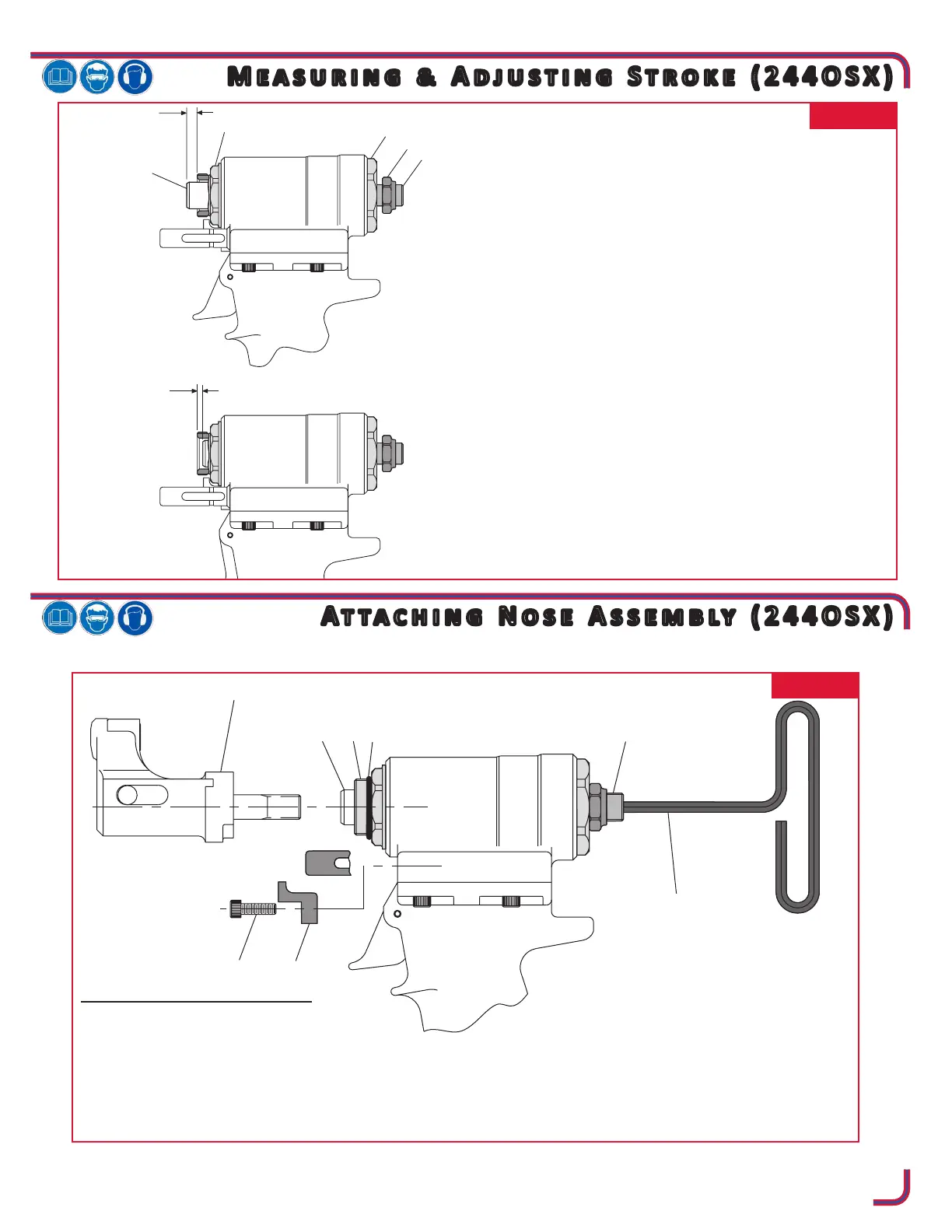
FIG. 12
ATTACHING NOSE ASSEMBLY
1. Remove Cap Screw (91) and Rotational
Stop (90).
2. Insert a 3/16” hex T-Wrench through Piston
Stop (89) until it engages internal hex in Hydraulic Piston (18).
3. Thread the nose assembly onto the tool until it bottoms out. Then back it off half to one full turn.
4. Install Rotational Stop (90) and secure with Cap Screw (91). The nose should be free to rotate approxi-
mately 45 degrees from the vertical in either direction (90 degrees included).
FIG. 11
ADJUSTING STROKE
1. Measure distance “A” from face of Hydraulic Piston
(18) to face of Nose Adapter (9). This distance should
be approximately equal to .247 inches.
2. Cycle tool and hold piston back by keeping the trigger
depressed. Measure distance “B” as above.
3. STROKE = A+B
4. Adjust Piston Stop (89) clockwise to reduce dimen-
sion “B” (decreasing stroke) and counterclockwise to
increase “B” (increasing stroke). Repeat step 2.
5. When desired stroke has been reached, hold Piston
Stop (89) with a ¼” hex key and with a ¾” open end
wrench tighten Locknut (92) against End Cap (21).

 Loading...


