244 series Pneudraulic Installation Tools (HK989)Alcoa Fastening Systems & Rings
9
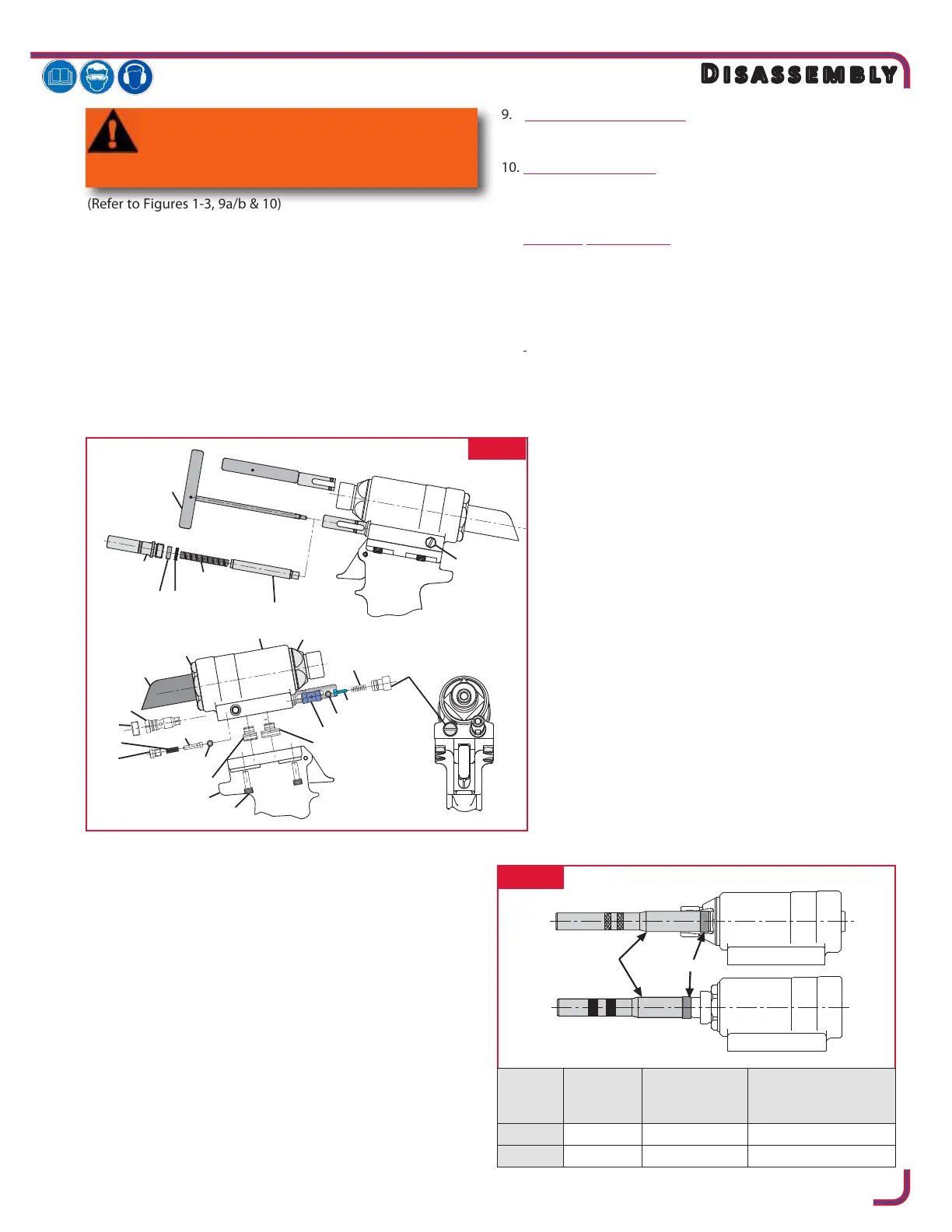
(Refer to Figures 1-3, 9a/b & 10)
NOTE: The following procedure is for complete disassembly
of tool. Only disassemble the components necessary to
replace damaged O-rings, Quad-Rings, Back-up Rings, and
worn/damaged components. Always use soft jaw vice to
avoid damage to tool.
1. Disconnect air hose from tool.
2. Remove nose assembly.
3. Insert Fill Tool through reservoir housing and screw into
Reservoir Plunger, locking it in the out position (Fig1).
4. Unscrew 4 Cap Screws with 5/32 hex key. Carefully lift Head
straight up from Handle. Remove Pull and Return Gland
Assemblies from separated head / handle (Fig1).
5. Unscrew Relief Valve Plug. Remove Relief Valve Spring,
Guide, Sleeve and Steel Ball. A small magnet is helpful.
6. Unscrew Reservoir Fill Plug. Hold over waste oil container
and release ll tool slowly (Fig1).
7. Unscrew Reservoir Housing/Spacer Assembly. Remove
2 Springs between housing and plunger. Slide Reservoir
Plunger from head. Remove Spacer and Quad-Ring (a pick
may be used to remove the Quad-Ring).
8. Unscrew Check Valve Plug, Spring, Guide, and Stainless
Steel Ball (Fig1).
9. 244X only (Fig. 1, 9a, 10)
Pintail Deector can be pulled at rear of Tool.
10. 244X: (Fig. 1, 9a, 10)
Unscrew End Cap (21) from Head, Plug & Seat Assembly
(15) with 1 9/16 open end wrench.
244OSX: (Fig. 1, 9b, 10)
Loosen and remove Locknut (92) from Piston Stop (89).
Unscrew Piston Stop (89) from End Cap (21), then unscrew
End Cap from Head, Plug & Seat Assembly (15) with 1 9/16
open end wrench.
11. (Fig2) Place spacer over front of piston and thread piston
Assembly Tool onto Piston. Tap or press piston assembly
out of head. NOTE: This action will also push out front
and rear gland assemblies.
12. Pushing the piston out of the tool causes rear
gland/sleeve assy (Item 19, Fig. 9a/b) to be pushed
out as well. Slide sleeve o of piston in order to
replace seals on piston and to replace O-ring (Item
103, Fig. 9a/b) inside cylinder head.
13. Remove Nose Adapter (9) from front of Head, Plug &
Seat Assembly (15). (Figs. 1, 9a/b & 10).
14. If Seat (74) is damaged, contact your Huck
representative. If Seat Assembly (80) is damaged, it can be
removed by using Seat Removal Tool (126136) optionally
available. NOTE: Seats should not be reused. They
should be replaced.
15. With a small punch and hammer, drive Roll Pin (4) that
retains the Trigger (5) from the Handle. Remove Trigger
Pin (3). Remove ball cable end from Throttle Arm (68) and
pull Cable Assembly (2) out of Handle. (Fig. 3)
16. Remove Pivot Screw (64) and Lever Guard (94) from
Throttle Arm (68). Remove Throttle Arm. Pull Throttle
Valve (67) out of cylinder. Remove Spring (65) (Fig3).
FIG. 1
FIG. 2
WARNING: Be sure air hose is disconnected
from tool before cleaning, or performing
maintenance. Severe personal injury may
occur if air hose is not disconnected.