14
244 series Pneudraulic Installation Tools (HK989) Alcoa Fastening Systems & Rings
Step 6
Connect tool to shop air 20 to 40 psi. Cycle tool 20-30
times, watch for air bubbles escaping from the tool into
bottle. (You may rock the tool to free trapped air in the
tool.) Do not allow the air to re-enter the tool. When
cycling tool, always hold bottle up as shown in Figure 8 to
prevent drawing in air from empty part of bottle.
Step 7
When air bubbles no longer appear in bottle, remove ll
bottle while tool is lying on its side.
Step 8
Install the check valve Ball (75), Check Valve Guide (76) and
Spring (77). Replace the Plug (78).
Step 9
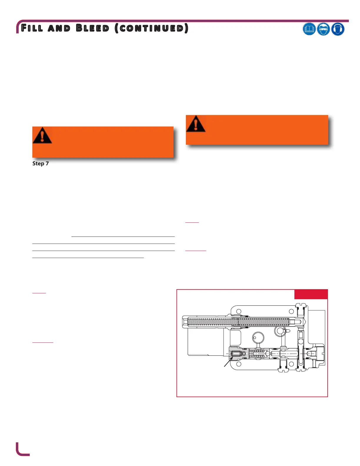
Turn tool so front of head faces you and remove the relief
valve Plug (85). Prior to removing Plug (85), it is advisable
to back out setscrew inside of plug by approximately 1/2
turn counterclockwise. (See Figure 8a). This ensures that
the Piston will remain in full-forward position. Install relief
valve Ball (81), Guide (82), Sleeve (83) and Spring (84).
Replace the Plug (85).
Step 10
244X (Fig. 8)
Unlock Fill Tool and check Reservoir red line. At this point
cycle the tool the with Stall Nut attached and retaining
nut locked in the full forward position (“Dead Stall”).
Reservoir should not drop below the red line on the res-
ervoir housing.
244OSX (Fig. 8)
Unlock Fill Tool and check Reservoir red line. At this point
cycle the tool with the Stop still holding the piston in the
full forward position (“Dead Stall”). Reservoir should not
drop below the red line on the reservoir housing.
Step 11
Re-lock the ll tool. Lay tool on its left side and remove
Plug (40). Top o reservoir by placing a few drops of oil in
hole and waiting for air bubbles to escape. Push a pin or a
scribe into hole to check for trapped air bubbles. Replace
plug.
Step 12
Unlock the ll tool and cycle tool as in step 10. Reservoir
may drop slightly. If so, repeat step 11 until when you
touch the ll tool handle, it has no pressure against it and
it drops out of the lock position, and the plunger does not
drop when tool is cycled. NOTE: This usually requires 3
to 4 times topping o.
Step 13
244X (Fig. 8)
Remove ll tool and stall nut. Install a nose assembly and
pull several fasteners to test function.
244OSX (Fig. 8)
Remove ll tool. Adjust the tools stroke for the Nose
Assembly being used by threading out Piston Stop (89).
Refer to Measuring Tool Stroke section for the stroke
adjustment procedure.
FIG. 8a
-
 Loading...


