Chapter 3 • Pointing the antenna by using the DAPT3
1039429-0001 Revision D
8. Enter the site latitude and longitude GPS values.
9. Select the appropriate satellite from the drop-down menu.
10. Select the appropriate model for the BUC/LNB.
11. Check the Enable TX Voltage checkbox if you will use the DAPT3 during the
install. If you put the IDU into pointing mode without checking this box, the
DAPT3 will not power on and you will not be able to successfully complete the
modem registration process.
12. For installations where the BUC uses an external power supply, you still need
to initially check this box in order to use the DAPT3. But in this case, once you
have completed the cable calibration and acquired the pointing parameters
(as described in the next section, Pointing on page 29), you will need to return
to the modem and reinstall with the TX voltage disabled (leaving the Enable
TX Voltage checkbox unchecked). For the Calibration Type, select Automatic
or Manual.
13. If you chose Automatic, continue to step 17. If you chose Manual, proceed to
step 14.
14. Type the cable loss (measured in dBs) in the field next to the Manual radio
button. The value cannot be higher than 18.
15. Click Submit. The satellite modem saves the information and enters into the
pointing mode.
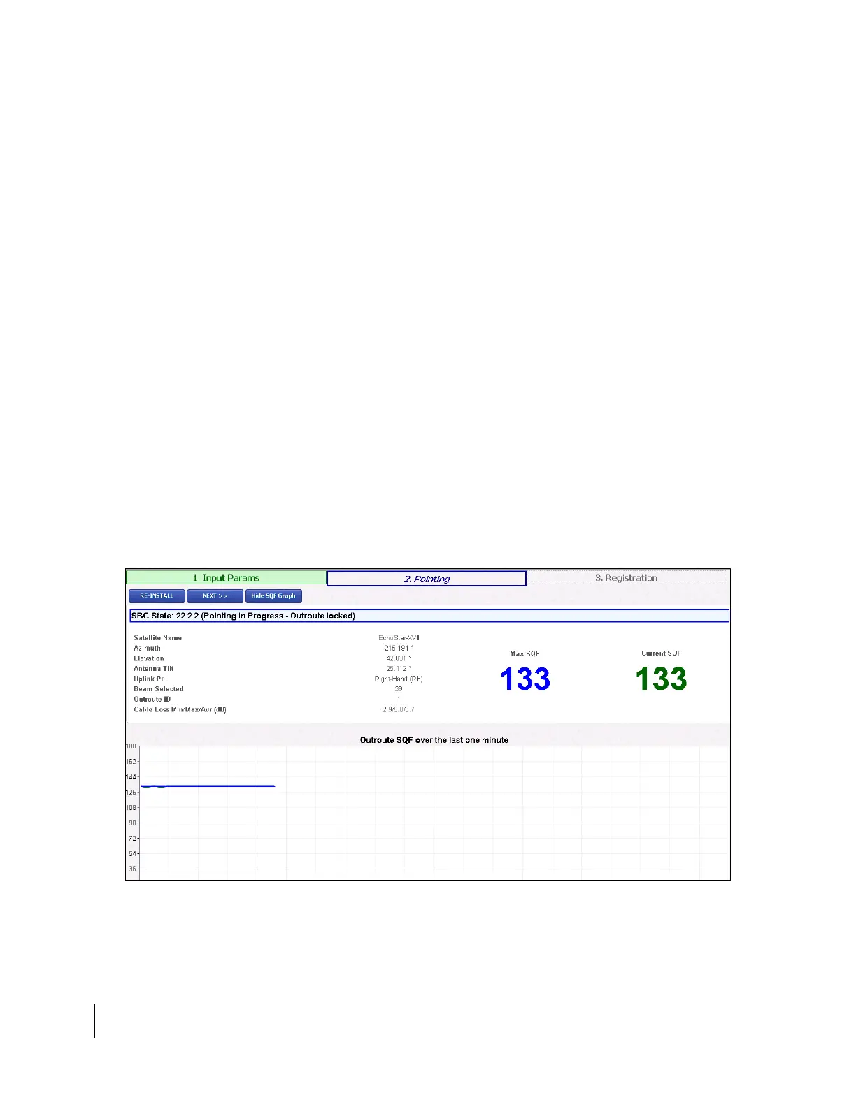
16. The Pointing Info screen appears on the installer laptop, as shown in Figure 7
on page 16.
Note: If you modify any existing parameters, the modem reboots, and the
Terminal Pointing screen will appear following the reboot. To return to
the Input Parameters screen at any time, click Re-Install.
Figure 15: Pointing Info screen