22
41524-01 9-5-2001
®
If your fan has a lower switch hous-
ing as shown in Figure 9c and you
ARE NOT installing a light fixture, or
if your fan has a lower switch hous-
ing as shown in Figure 9d or 9e,
complete the following steps:
1. Connect the upper plug connec-
tor from the motor to the lower
plug connector in the lower
switch housing assembly. See Fig-
ure 9f.
Note: Both plug connectors are
polarized and will only fit together
one way. Make sure that both
connectors are properly aligned
before connecting them together.
Incorrect connection could cause
improper operation and damage
to the product.
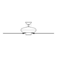
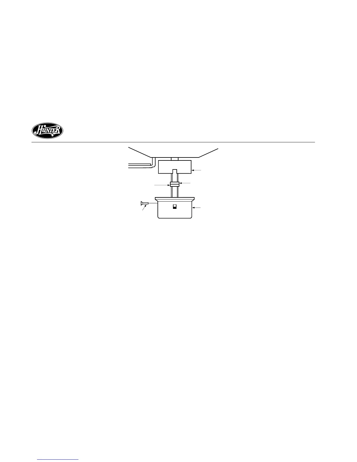
Figure 9f - Plug Connection and
Lower Switch Housing Installation
Upper
Switch
Housing
Upper Plug
Connector
Lower Plug
Connector
Lower
Switch
Housing
Housing
Assembly
Screw
2. Place the lower switch housing
assembly over the upper switch
housing. Align the side screw
holes in the upper and lower
switch housings. Attach the lower
switch housing to the upper
switch housing with three #6-32
x 3/8" housing assembly screws.
See Figure 9f.
Note: If your fan does not include
a light fixture, you may purchase
an accessory light kit separately.
See STEP 10 - INSTALLING LIGHT
FIXTURE.