51 52
Learn more. Visit hunterindustries.com/golf
TABLE OF CONTENTS I PILOT VALVE REPLACEMENT
SOLENOID & PILOT VALVE ASSEMBLY REMOVAL I TABLE OF CONTENTS
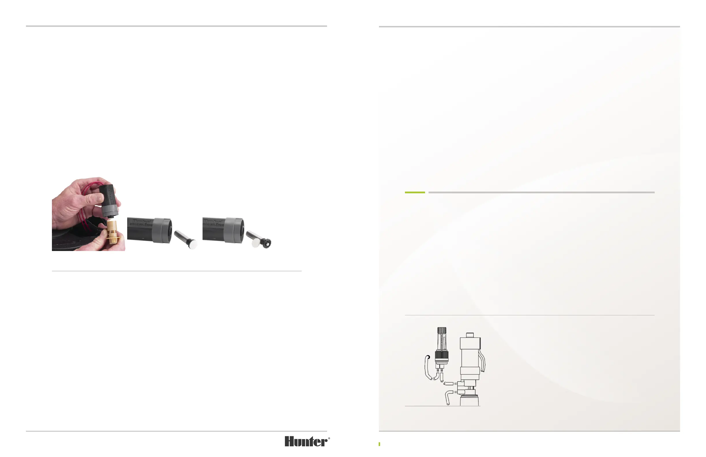
The plunger assembly is retained within the Solenoid with a secure snap-t feature. To remove the
plunger assembly, rst notice there is a black knurled ring just below the solenoid’s rubberized
seat-seal. Just below the black knurled ring is a black O-Ring. The plunger assembly can be removed
by forcing the thumb-nail under the black knurled ring and pulling to separate the plunger
assembly from the solenoid (FIGURE 134). Alternatively, a small at bladed screwdriver can be
inserted below the black knurled ring and twisted to release the plunger assembly. Use care not to
damage the black O-Ring. If the plunger assembly does not stay assembled when removed from
the solenoid, it is necessary to replace the Plunger assembly.
Rinse the plunger assembly and solenoid with clean water to remove any contaminating debris. If
damage or worn, replace black O-Ring and/or rubberized seat-seal (FIGURE 135). Insert plunger
assembly into the solenoid and then press to engage the snap-t feature. Finally, press on the
seat-seal to cycle the plunger assembly. If plunger does not cycle up and down freely, repeat
cleaning procedure and/or replace the plunger assembly.
Solenoid Replacement – It is not necessary to dig around the rotor to replace in-ground solenoid
wire splice connections if there is condence in both the quality of the splices and the type of
connector used. It is absolutely not necessary to dig around the rotor to replace the solenoid wire
splice connections if the original connecting splices were completed within the rotor’s ange
compartment.
In-ground with questionable wire splice connections – dig around the rotor to access the solenoid
splice connections. Remove the connectors. If possible, run controller wires into the rotor’s ange
compartment and splice wires to solenoid’s wires using appropriate grease-lled connectors.
If not possible, feed replacement solenoid’s wiring through hole at the bottom of the ange
compartment. Splice controller wires with solenoid’s wires using appropriate grease-lled
connectors. Choose either of the Hunter DC solenoid’s lead wires when making each splice as
there is no specic polarity required.
IMPORTANT – the TTS rotor’s top service capabilities require that there is sucient slack in the
Solenoid’s wiring leads within the ange compartment. To estimate required wiring slack, bring
Solenoid to the top of the rotor’s ange. During back-ll of soil around rotor, do not let the
Solenoid be pulled into the ange compartment.
In-ground good quality wire splice connections –
Hold the defective solenoid in one hand and
cut the defective Solenoid’s two lead wires at
a point close to the defective solenoid. Splice
the lead wires from the defective solenoid to
the new solenoid’s lead wires using appropriate
grease-lled connectors. If needed, the new
Solenoid’s lead wires can be shortened to
minimize excess wiring within the ange
compartment.
Flange compartment wire splice connections –
If original wire splice connections were made
within the ange compartment, simply disconnect
splices and re-splice controller wiring to the
new Solenoid’s wiring leads. Conrm that
appropriate grease-lled type connectors are in
use. If not, discard and replace with appropriate
connectors. If needed, the new Solenoid’s lead
wires can be shortened to minimize excess
wiring within the ange compartment.
PILOT VALVE REPLACEMENT
See the warning above regarding rotor activation
when Solenoid is loosened or Pilot Valve tubing
is disconnected. There are no serviceable parts
within the TTS rotor’s Pilot Valve assembly. If
the lter inside the Pilot Valve becomes
obstructed, the water ow through the Pilot
Valve can be reduced. A substantial reduction in
water ow through the Pilot Valve will prevent
the rotor’s Inlet Valve from opening fully.
Notice the two tubes attached to the Pilot
Valve’s ttings (FIGURE 136). The lower tting is
the inlet and the upper tting is the outlet. The
lower tube is the pressurized supply tube that
comes from the rotor’s Inlet Valve at the bottom
of the rotor. The upper tube goes from the Pilot
Valve to the inlet of the pressure regulator. To
replace the Pilot Valve, use side-cutters or blade
to make clean cuts at points just before the
ttings on the Pilot Valve. Trim & remove the
remaining tube from ttings.
FIGURE 133 FIGURE 134 FIGURE 135
FIGURE 136

 Loading...