27 28
Learn more. Visit hunterindustries.com/golf
TABLE OF CONTENTS I RISER REPLACEMENT
STATOR ADJUSTMENTS I TABLE OF CONTENTS
STATOR ADJUSTMENTS G90 & G95 RISERS
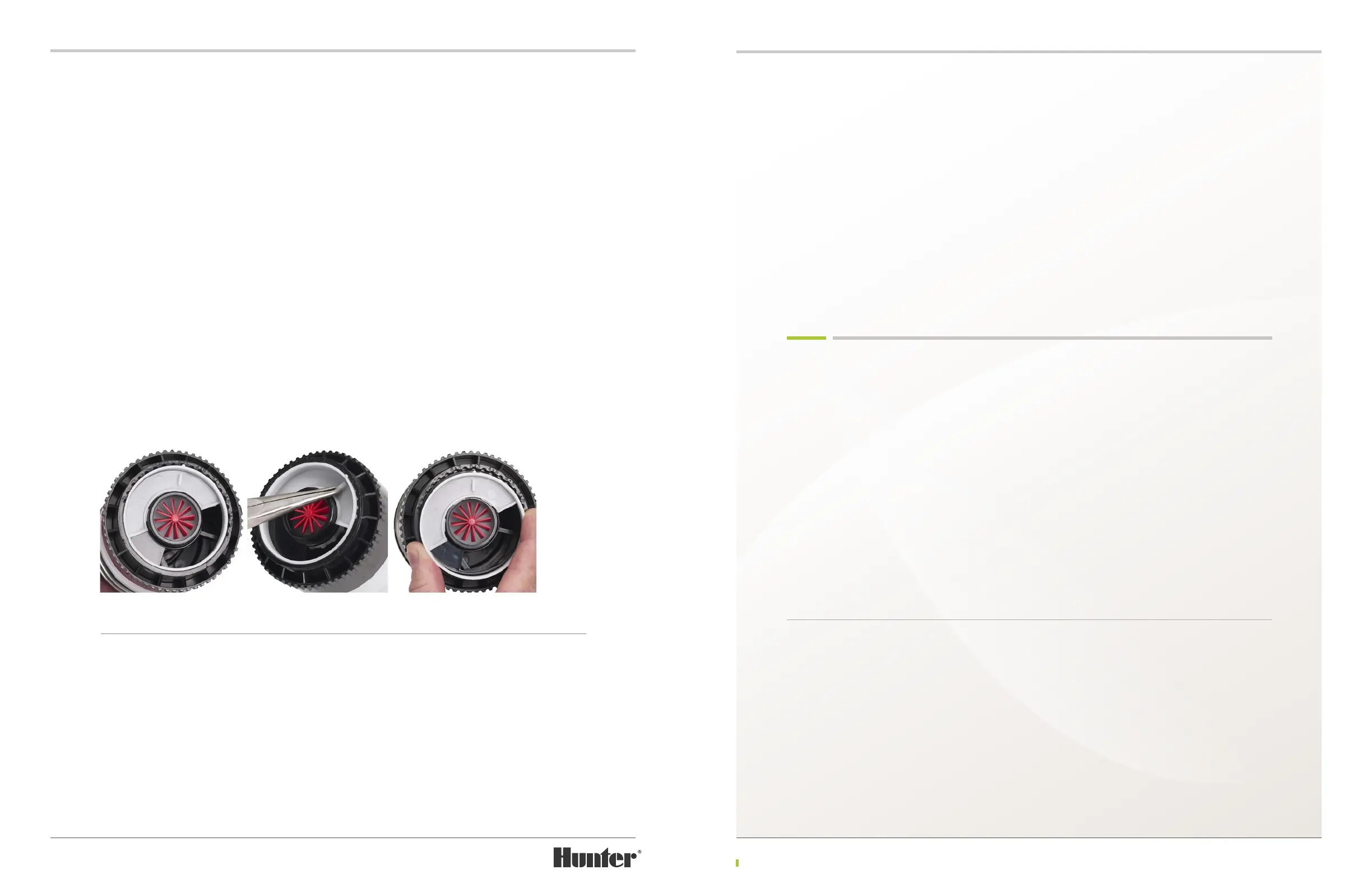
Turn the riser upside down, remove the lter screen and view the stator area. Notice the white
plastic part that is set within the bottom of the riser (FIGURE 62). This white part on G90 and G95
risers is called the adjustable stator plate. Beneath the adjustable stator plate is a black non-
removable plastic part with the opening in the center for the turbine and the single opening to the
side. This part is called the stator. The outer ring at the base of the riser has recessed notches all
the way around it. Notice that the white adjustable stator plate has a protrusion that is engaged
with one of these recessed notches. This protrusion is the adjustable stator plate’s pointer. Also
notice there is a series of numbers engraved into the plastic next to some of the recessed notches.
These numbers are the nozzle size reference numbers.
To make an adjustment, rst nd the raised wall or blade of plastic on the adjustable stator plate.
Use pliers to grab the plastic blade then pull to remove the white adjustable stator plate from the
riser (FIGURE 63). To reset and install the adjustable stator plate, nd the nozzle size reference
number on the outer ring that matches the installed nozzle. Simply align the pointer on the
adjustable stator plate with the desired nozzle number on the outer ring. The pointer can be
placed on either side of the nozzle reference number (FIGURE 64). Next, snap the adjustable
stator plate down and into position. Once the adjustable stator plate is installed, check to make
sure the desired nozzle size reference number aligned with the pointer. Finally, install the lter
screen as outlined above.
RISER REPLACEMENT FULL-CIRCLE RISERS
Full-circle riser assemblies can be inserted into the rotor’s body without regard to arc orientation.
Insert the riser, screen rst, into the rotor’s body until it comes to a stop. Next, install the upper
snap-ring referencing instructions which follow for your rotor model.
RISER REPLACEMENT G35, G75 & G95 ADJUSTABLE PART-CIRCLE RISERS
Adjustable part-circle risers must be inserted
such that the arc setting aligns to the area to
be irrigated. All Hunter adjustable arc rotors
have a xed stop on the right side of the arc
and an adjustable stop on the le side of the
arc. Rotate the nozzle housing (turret) back and
forth to nd the right xed stop. With the riser
positioned to the right xed arc stop, orient and
point the long-range nozzle to the right side of
the landscape area to be irrigated. Drop the
riser into position within the rotor’s body.
For convenience of installation, new rotors from
the factory are set to approximately 180 degrees
and the long-range nozzle is positioned to the
right x side of the arc. Arc adjustments can be
made with the riser in hand before installation,
aer installation, or while the rotor is in
operation.
Refer to the page 13-14 in this manual to learn more about the arc adjusting procedures.
UPPER SNAPRING INSTALLATION TIPS
Hunter Golf TTS rotors have upper snap-rings
with an integrated wiper to help protect the
riser and riser seal from external contamination.
It is important to follow these installation
instructions to maximize the eectiveness of
this design.
First, it is important to align snap-rings so that
the open end of the snap-ring is not adjacent
to (next to) the ange compartment. This will
become very important the next time the snap-
ring is removed. If the ange compartment lid
has been removed and the open end of the
snap-ring is adjacent to (next to) the ange
compartment, it will be very dicult to remove
the snap-ring using the snap-ring tool. For
better leverage when removing the snap-ring,
always align the open end of the snap-ring in a
position that is opposite from the body’s ange
compartment.
The second tip for upper snap-ring installation
concerns the rubberized aps at each end of the
snap-ring. To ensure that these rubberized aps
lie at aer installation, it is important to install
the snap-ring correctly. Once installed, the ap
on the le end of the snap-ring must be under
the ap on the right-side end of the snap-ring.
FIGURE 62 FIGURE 63 FIGURE 64

 Loading...