9 10
TABLE OF CONTENTS I RISER REMOVAL
UPPER SNAPRING REMOVAL G900 SERIES
Prior to removal of the upper snap-ring assembly, the rubberized logo cap must be removed and
the riser assembly must be pressed below the snap-ring’s rubberized seal. If the procedure below
is not followed, the upper snap-ring assembly cannot be removed from the G900 Series rotors:
Remove the stainless screw from the center of the rubberized logo cap using a Phillips screwdriver
(FIGURE 10). Prior to removing the rubberized logo cap, note that the arrows on the logo indicate
the position of the nozzles on the riser assembly. As the rubberized logo cap is removed, note
there is a protruding pin on the underside of the logo cap (FIGURE 11). This pin is the alignment
feature on the rubberized logo cap that must be inserted correctly during assembly in order for
the arrows on the rubberized logo cap to be positioned over the nozzles below. Note which hole
the pin ts into on top of the riser (FIGURE 12). Also note that the pin and hole locations are
dierent for the G90 and G95 risers.
Once the rubberized logo cap is removed, use the heel on the palm of your hand to forcefully press
the riser assembly down (FIGURE 13) and below the rubberized wiper seal on the snap-ring assembly
(FIGURE 14). When the rotor is dry (without water within) more force is required. If sprinkler is
installed and has been activated, the water acts to lubricate the wiper, making the procedure
much easier.
Learn more. Visit hunterindustries.com/golf
UPPER SNAPRING REMOVAL I TABLE OF CONTENTS
To remove the snap-ring assembly, hold Snap-
ring Tool vertical over the rotor’s upper snap-
ring area. Align the metal end of the snap-ring
tool to the indicator on the snap-ring’s rubberized
wiper seal (FIGURE 15). Use the palm of the
other hand to drive the tool downward &
through the rubberized membrane (FIGURE 16).
Tool should penetrate about ¼ inch into the snap-
ring assembly. While holding the tool within the
snap-ring, press the tool’s handle downward and
away from the center of the rotor. As the tool is
pressed downward, the snap-ring will li from
the rotor. While using the tool to hold the snap-
ring in this elevated position, use the other hand
to pull the snap-ring from the rotor (FIGURE 17).
If the snap-ring’s rubberized wiper seal appears
to be the only part that is liing, the tool has not
penetrated into the snap-ring far enough.
FIGURE 10
FIGURE 13
FIGURE 11
FIGURE 14
FIGURE 12
FIGURE 15
FIGURE 18
FIGURE 16
FIGURE 19
FIGURE 17
FIGURE 20
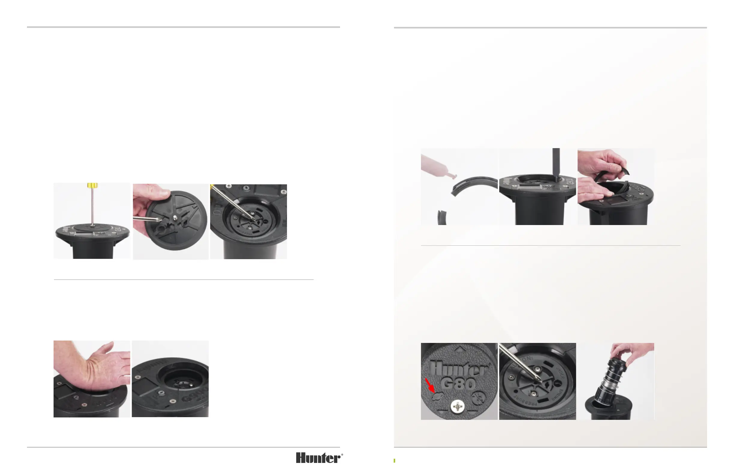
RISER REMOVAL ALL MODELS
To remove the riser assembly, rst remove the
upper snap ring as outlined above. Insert the
Hunter Wrench, T-Handle Tool or tip of the
Snap Ring tool into the riser’s li socket, turn ¼
turn and li the riser from the rotor’s body. The
li socket for G835, G870, G875, G880, G884
and G885 models is protected by a rubberized
membrane on the rubberized logo cap and can
be located by nding the raised line depiction of
the socket’s shape (FIGURE 18). G990 and G995
risers have a removable rubberized logo cap so
the li up socket is accessed aer removing the
logo cap, directly on top of the riser (FIGURE
19). In some cases, the riser can simply be pulled
from the rotor’s body by hand once the upper
snap-ring assembly is removed (FIGURE 20).

 Loading...