nt
r
• D
Electric
7.
ach batter
bank is wired to a batter
selector switch
located under the chart table. A circuit breaker “DC Main”
n the batter
switch panel connects the batteries to the
lectrical s
stem. The batteries suppl
power,
irst to
the batter
selector switch then to the 12 Volt DC Panel
which distributes power to such equipment as cabin
li
hts, instruments, and accessories.
The ne
ative terminal o
all banks are attached to the D
round connection on the en
ine. This s
stem, known as
the ne
ative
round s
stem, is the approved s
stem for
marine D
electrical s
stems. The batter
wirin
s
stem
has two color coded wires. The
ellow wire is the
round
ne
ative
, and the red wire is
positive
.
To avoid explosions, do not use
umper cables and a
booster batter
to start the en
ine. If batteries are dead,
then remove and rechar
e them ashore
atter
es pro
uce
ro
en an
ox
en
asses w
en
the
are bein
char
ed. These explosive
asses escape
throu
h the vent
ill caps and ma
orm an explosive
atmosphere around the batter
if ventilation is poor. This
as ma
remain around the batter
or several hours a
ter
har
in
.
parks or
lame can i
nite the
as and cause
an ex
os
on
The
ollowin
precautions must be taken
The wirin
to the batteries must have proper over
current protection in the
orm o
use or breakers
se onl
batter
char
ers that have been listed b
a
testin
a
enc
, such as Underwriters Laboratories,
n
Follow the wirin
dia
rams exactl
o remove the batter
Turn off all power drawin
breakers and isolate bat-
er
.
emove ne
ative
-
cable first, then the positive
+
When
ou install a batter
, the batter
connections must
e ma
e proper
Attach the positive cable to the positive
+
terminal
n t
e
atter
Attach the ne
ative cable to the ne
ative
-
terminal
1
2
n the batter
Note: Batteries should always be removed and installed by
trained, qualified persons to avoid all damages.
Table 1 Recommended Batteries
or equivalent
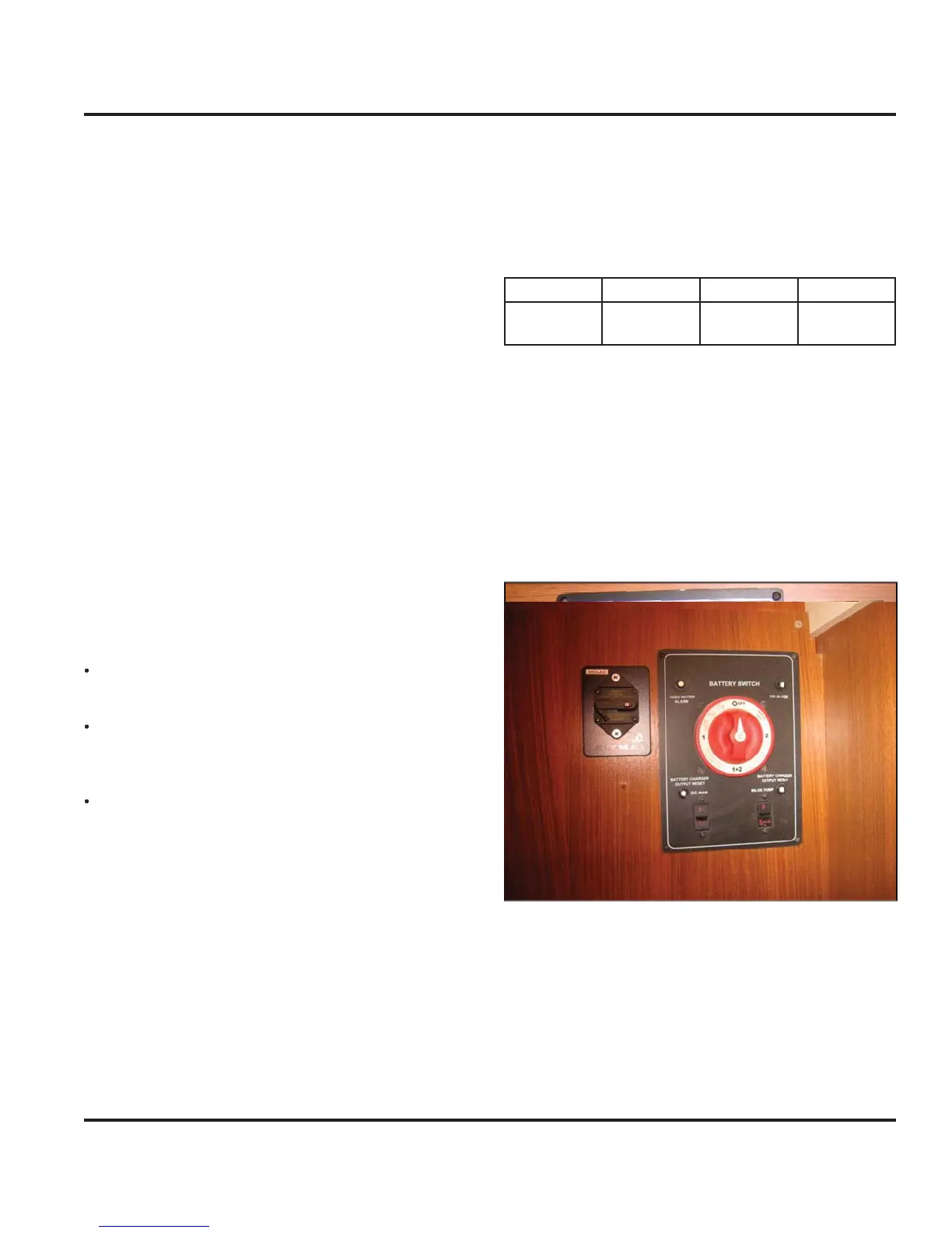
7.2.2 Batter
Switch Panel
e
atter
an
s are connecte
to a
atter
se
ector
switch
Fi
. 7.1 shown without optional inverter
located
n
r th
h
rt t
l
.
The selector switches are marked as to which batter
the
control. Turnin
the selector switch to the
posi-
tion turns
ower off to the res
ective circuits, likewise, the
n position turns power on.
Fi
ure 7.
The batter
switch panel houses the breakers
or some
f the main components in
our DC s
stem. The breaker
ontrols are marked at the switch panel, and control s
s-
tems or components on
our boat that require a connec-
t
on t
at rema
ns ener
ze
even t
rou
t
e
a
n
ane
ma
be de-ener
ized
e
rea
ers an
sw
tc
es are
escr
e
n
reater
eta
in the
Breakers and
witches” section o
this chapter
F
PN
roup
iz
lt
t
Exi
Pr
-
v
il
r PV-
1