nt
r
• D
Electric
7.4
7.2.3 Batter
Char
in
S
ste
e
er to the D
Wirin
Dia
ram drawin
at the end o
this section for the location of the batter
char
er. The
har
er is protected b
a
use on the positive and
round
side at the char
er.
o operate the char
er, ensure that it is operatin
onnect the shore power dockside suppl
shore
power inlet on the stern o
the boat on the port side.
Turn on AC Main breaker
Turn on the Batter
har
er breaker
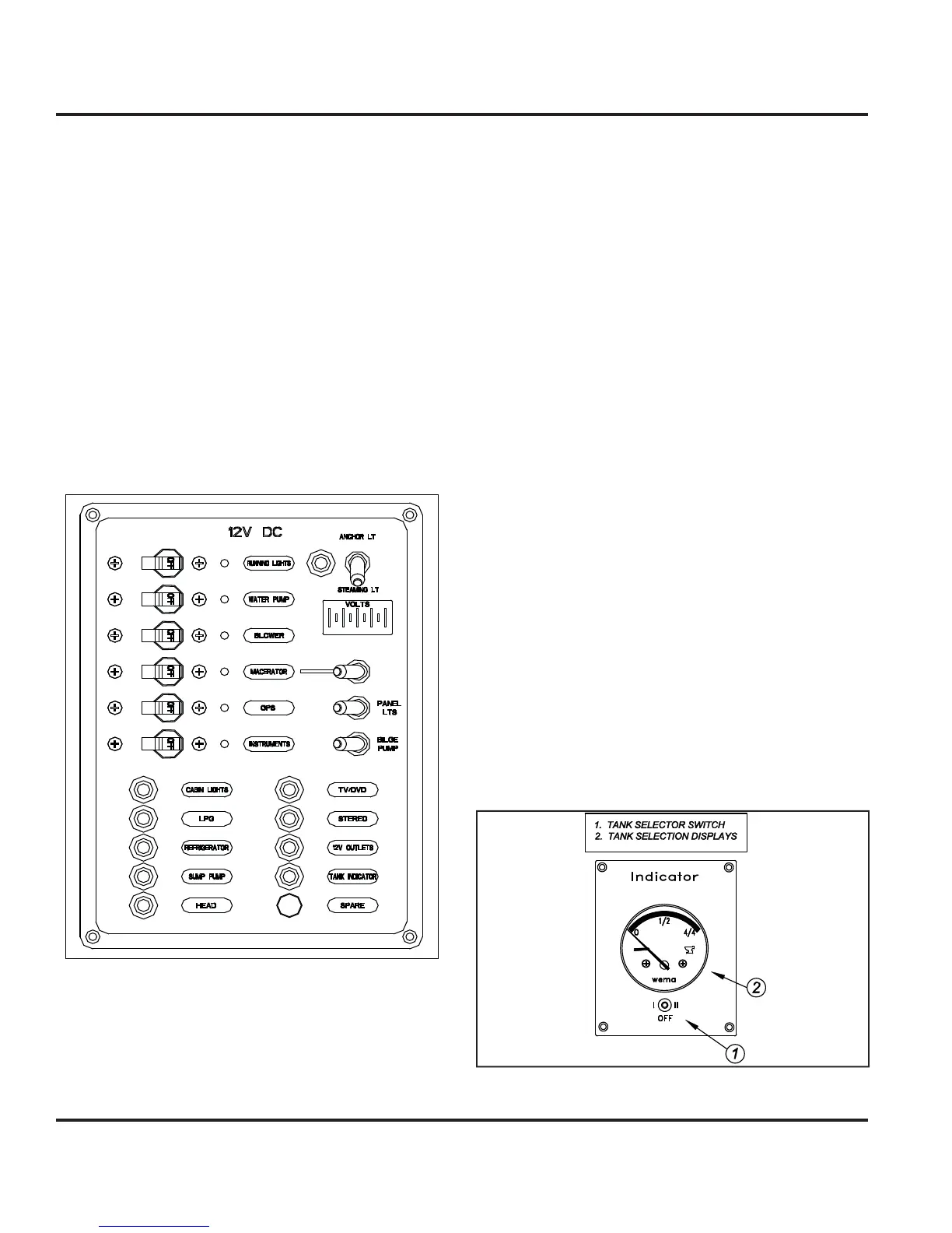
7.2.4 12 Volt DC Panel
Fi
ure 7.2
You can view the D
components controlled b
the D
ontrol panel here
Fi
. 7.2
. Indicator li
hts are built into
most sw
tc
es an
a
ert
ou t
at t
e se
ecte
s
stem
s
powered
7.2.5 Breakers, Switches, and Fuse
e
ectr
ca
s
stems a
oar
our
oat are prov
e
w
t
ver-current protection in the
orm o
breakers or
uses.
xamples o
breakers are the s
stem or component con-
trols at the 12 Volt Panel, or in the batter
selector switch
panel.
stems that would normall
require
ou to ener-
ize them
or use are provided with switches
7.2.6 Inverter
Option
Inverter converts DC
ower to AC.
7.2.6.1 Inverter Basic O
eration
1. Turn the house batter
switch to either the
1, 2 or
Both
positions
. Turn on inverter remote panel at the Navi
ation
tation
. Turn on the appropriate appliance breaker on A
n
l.
ee Inverter manual
or technical data, troubleshootin
,
tc. operatiin
pro
rammin
instructions
7.2.7 Water S
stems
The water s
stems are outlined in the Water S
stems
hapter in this manual. However, the controls and
monitors
or these s
stems are all powered b
the D
ectr
ca
s
stem.
The water tank monitor as shown in Fi
. 7.3 allows
ou
to se
ect t
e tan
to mon
tor t
e water
eve
n t
e respec-
tiv
t
nk.
Fi
ure 7.