Other Controllers
The
two
most common
situations are shown below.
For non-standard wiring
situations, please consult
your distributor or request
our "Non-standard"
wiring information packet.
A.
24 Volt Solenoid Valves
Only (No booster pump)
(See Figure
3)
With the two wires from
the Mini-Ciik at the
controller, locate the
"common ground" wire of
the solenoid valves_ If it is
connected to the common
terminal
cin
the controller,
disconnect it. Attach one
wire of the Mini-Ciik to the
"common" terminal
{usually marked "C") on
the
controller. Attach the
other
Wire
of the Mini-Ciik
to the common wire
leading to the valves.
Note: The common wire
·
to
the
Valves
does
not
have
to
be interrupted
at
the controller. The
Mini-Ciik may be wired
anywhere along the
commOn wire line.
B.
24 Volt Solenoid Valves
with Booster Pump {See
Figure 4)
Locate the common wire
to the solenoid valves
and
the common wire leading
to the coil of the relay that
starts the pump. If these
two wires are connected
to the
"common"-terminal
· on the controller,
disconnect both of them.
Twist together these two
wires along with one wire
from the Mini-Ciik, and
secure with a wire nut.
Attach the other wire of
the Mini-Ciik to the
"common" terminal
on
the
' controller. Note: The pump
circuit output
must
be
24
Volts in thi$ situation. Do
not
proce~d
if
110V
c.
Special Instructions for
Mini-Ciik-HV (See Figures
5 and 6)
The
two
taped and
stripped wires are the
ones to be used when
following these accompa-
nying diagrams. The third
wire should be terminated
with a wire nut (not sup-
plied). All wire connec-
tions with the Mini-Ciik
should be made with wire
nuts and located
in
a
junction box.
Where the timer is
controlling a pump, the
relay may be inside the
Mflli-Ciik
Contr611er
i
~
L_,_,
LL,...--,=-:-----'--'-'-'+1!1:
Valves
'
Common
Wire
to
AU
Valves
'.f
,Mini-Ciik Rain Sensors
Installation Instructions
tiriier, external or non-existent. If there is
no
relay
in
the circuit, one must be
added:The
"wiring for an internal
or
external relay is the same: the Mini-C!ik
breaks
the·
circuit to the coil of the relay only. Either wire of the coil may be
broken.
Operation Check
to
Verify Correct Wiring
Turn
on
one zone of the irrigation system that is visible while you are
in
reach
of the Mini-Ciik. Manually depress the spindle at
t~e
top of the Mini-Ciik until you
hear the swit-
·1
"c:!ick" off. The sprinkler zonr} sho"uld.stop instantaneously. If it
r
does
_jt.::it,
check
wiring for correctness. It is hot necessary to "wet" test the Mini-
Cii!<.,
although it will test the operation fine,
if
desired.
,,
DJUSiliMENTS .AND
OPERATION
I
Figure 3-
.!
~=========::;
l
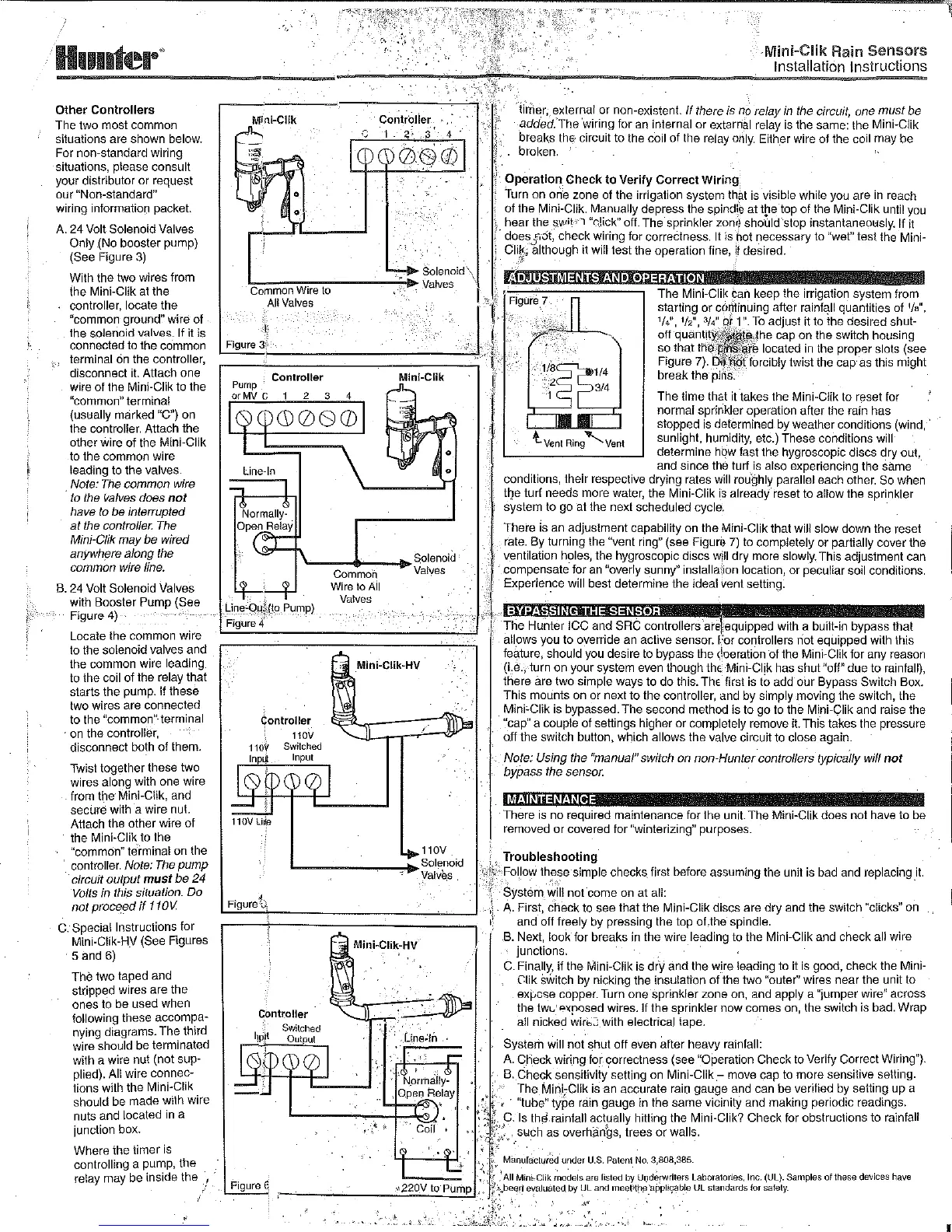
The
Mini-Ciik can keep the irrigation system from
starting or cof1tinuing after
rainf~ll
quantities of
1/a'',
1
/4",
1f2",
3/4':
9J1
":To adjust it to the desired shut-
off
quantityi\~~-':the
cap
on
the switch housing
so that the
rr~~r~
located
in
the proper slots (see
Figure 7).
Di'd'tiot_
forcibly twist the cap· as this might
break
the
pins.
Controller
2 3
Mini-Ciik
'----4>----1,.
Solenoid
Va!yes
Une-Q.u~_(to
Pump)
Figure 4
Controller
110V
Commoh
WiretoA!I
Valves
110V
L-------•
Solenoid
Valves
Figure"t~,
Mini-Ciik-HV
' '
!
I
't
L________:____J
The time that it ·takes the Mini-C!ik to reset for
norma! sprinkler operation after the rain has
stopped is determined by weather conditions (wind,
-lvent
Ring,Vent
sunlight, humidity, etc.) These conditions will
determine how fast the hygroscopic discs dry out,
and
since the turf is also experiencing the same
conditions, their respective drying rates
will rou"ghly parallel each other. So when
t~e
turf needs more water, the Mini-Ciik
is
already reset to allow the sprinkler
system to go at the next scheduled cycle.
There
is an adjustment capability on the Mini-Ciik that will slow down the reset
rate.
By
turning the "vent ring" (see Figun} 7) to completely or partially
cover
the
ventilation holes, the hygroscopic discs will dry more slowly. This adjustment can
compensate- for an "overly sunny" installa{ion location, or peculiar soil conditions.
Experie~ce
will best determine the idea! vent setting.
: . '
..
The
Huilter
ICC and SRC controllers are :equipped with a built-in bypass that
allows you to override an active sensor. For controllers riot equipped with this
feature, should you desire to bypass the
~be
ration of the Mini-Ciik for any reason
{i.e., turn
on
your system even though
thE
Mini-CI!k has shut "off"
due
to
rainfall),
there are two simple ways to
do
this.
ThE
first is to add
our
Bypass Switch Box.
This mounts on or next
to
the controller, and by simply moving the switch, the
Mini~Ciik
is bypassed. The second method is to
go
to the Mini-Ciik and raise the
"cap" a couple of settings higher
or
completely remove
it
This takes the pressure
6.ff
the switch button, which allows the valve circuit to close again.
Note: Using the "manual" switch on non-Hunter controllers typically will
not
bypass the sensor.
M.AINTEN.ANCE
·There
is no required maintenance for the unit.
The
Mini-Ciik does
not
have to be
removed or covered for "winterizing" purposes.
Troubleshooting
\;;·/,~=-
Follow these simple checks first before assuming the unit is bad and replacing
_it.
i
System will
not
come on at all:
.
A.
First,
check
to see that the Mini-Ciik discs are
dry
and the switch "clicks" on
and
off freely by pressing the top of.the spindle.
B.
Next, look for breaks
in
the wire leading
to
the
Mini-Ciik and check all wire
junctions.
C. Finally, if the Mini-Ciik is drY
and
the wire leading to it is good, check the Mini-
Ctik
SWitch
by nicking the insulation of the
two
"outer" wires near the unit to
exf:-cse copper. Turn
one
sprinkler zone on, and apply a "jumper wire" across
the
tw~..
Pxrosed wires. If
the
sprinkler
now
comes on, the switch is bad. Wrap
all nicked
wirb:::
with electrical tape.
System will
not
shut off even after heavy rainfall:
A.
Check wiring for correctness (see "OPeration Check to Verify Correct Wiring").
B.
Check sensitivity. setting on Mini-Ciik
.-
move cap to
more
sensitive setting.
The
Mini~Ciik
is
-an
accurate rain gauge and can
be
verified by setting up a
· "tube" tyPe rain gauge in the
same
vicinity and making periodic readings.
Is the!.rainfall actually hitting the Mini-Ciik? Check for obstructions
to
rainfall
such
as
overhiinbs, trees
or
walls.
Manufactured
under
U.S.
Patent
No.
3,808,385.
Figure
€
.
~
.'All
Mini·Ciik
~odels
are
listed
by
U!!derwriters
Laboratories,
Inc.
(UL).
Samples
of
lhese
devices
have
c----'----:C::~~:C:~t:J.'.
· (\beert
evaluated
by
ULand
meet-'l[le_"applit;:able
UL
standards
for
safety.
,,
..
.l
-~--
~··
• •
••
,_.

 Loading...