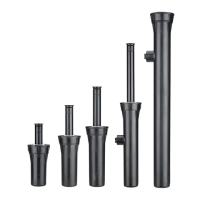
The kit is designed for PGP-00 and I-20-00. It allows
you to safely attach a shrub sprinkler to a piece of 5/16"
rebar. The kit comes with a heavy-duty locking tie to
attach the sprinkler to the kit.
NOZZLE INSTALLATION
1. Insert the plastic key end of the Hunter wrench into the
lifting socket of the sprinkler and turn 90˚. Pull the riser up
to gain access to the nozzle socket (Fig. 8).
2. Using the hex key of the Hunter
wrench, turn the radius adjustment
screw (Fig. 6) counterclockwise
to be sure it is not blocking the
nozzle socket opening. If a nozzle
is already installed, it can be
removed by backing out the
adjustment screw and turning on
the water, or by pulling outward
on the nozzle “ears” with a pair of
needle-nosed pliers.
3. Slip the desired nozzle into the
nozzle socket (Fig. 7). Note that
the socket is angled up 25˚. The
“ears” should be adjusted so that
the nozzle range screw threads
directly down between them.
Then tighten the nozzle range
screw. The raised bump with an
arrow on the rubber cover will
always indicate the location of
the nozzle and direction of water
ow when the sprinkler is retracted.
ALIGNING THE RIGHT (FIXED) SIDE OF ARC
If the right side of the arc is not properly aligned, the
results may be a wet walkway or a dry turf area. The
right side arc can easily
be realigned. One way to
realign the right stop is to
turn the whole sprinkler body
assembly and the tting
below it, left or right to the
desired position. This may
require temporary removal of
the soil around the sprinkler
to allow you to grip the
sprinkler housing.
Another way to reset the right
arc is to unscrew the body
cap counterclockwise and
remove the internal assembly
from the body. Once removed, rotate the nozzle turret
to the right stop, screw the internal assembly back into
the body with the nozzle aligned to the right side of the
area you want irrigated (Fig. 9). At this point you have
realigned the right arc stop, and you can adjust the left
arc to an appropriate setting.
Note: It is not necessary to dig up and remove the whole
sprinkler to realign the right arc.
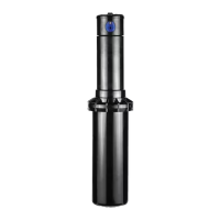
PGP INSTALLATION:
The PGP pop-up sprinkler should be
installed at nished grade as shown
in the illustration (Fig. 1).
Arc Adjustments:
Adjustable heads are preset to
approximately 180˚. Sprinklers may
be adjusted with water on or off. It is
recommended that initial adjustments be
made before installation.
1. Using the palm of your hand, rotate the
nozzle turret counterclockwise to the
left stop to complete any interrupted
rotation cycle (Fig. 2).
2. Rotate the nozzle turret clockwise to
the right stop. This is the xed side of
the arc. The nozzle turret must be held
in this position for arc adjustments. The
right stop does not change.
To Increase the Arc:
1. Insert the plastic key end of the Hunter
wrench into the adjustment socket (Fig. 3
& 4).
2. While holding the nozzle turret at the right
stop, turn the wrench clockwise. Each full
360˚ turn of the wrench will increase the
arc 90˚.
3. Adjust to any arc between 50˚ and 360˚
(Fig. 5).
4. The wrench will stop turning, or there will be a ratcheting noise, when the
maximum arc of 360˚ (full circle) has been reached.
5. When set to 360, the sprinkler will rotate continually counter-clockwise.
To Decrease the Arc:
1. Insert the plastic key end of the Hunter wrench into the adjustment socket
(Fig. 3 & 4).
2. While holding the nozzle turret at the right stop, turn the wrench counter-
clockwise. Each full 360˚ turn of the wrench will decrease the arc 90˚.
3. Adjust to any arc between 50˚ and 360˚ (Fig. 5).
4. The wrench will stop turning, or there will be a ratcheting noise, when the
minimum arc of 50˚ has been reached.
RADIUS / DISTANCE OF THROW
Insert the steel hex end of the Hunter wrench into the
radius adjustment screw (Fig. 6). Turn the screw clockwise
(into the stream of water) to decrease the radius, or coun-
terclockwise to increase the radius. Radius can be reduced
up to 25%.
PRECIPITATION RATE
ADJUSTMENT
If you have excessively wet
or dry areas, you can change
the nozzle in the sprinkler
to increase or decrease the
precipitation rate. For dry areas,
install a larger nozzle. For wet
areas, install a smaller nozzle.
DRAIN CHECK VALVE
All Hunter sprinklers are available with a factory-installed drain check valve.
The drain check valve prevents low-head drainage with elevation changes up to
10'. To order, specify PGP-00-CV or PGP-04-CV. All PGP-12 sprinklers come
standard with a drain check valve. If a check valve is added to the standard
PGP-04 in the field, the elevation check height will be approximately 4'.
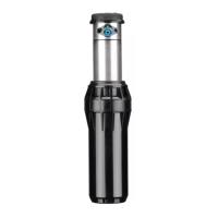
RECLAIMED ID
All Hunter rotors are available with a purple rubber cover permanently attached.
The purple cover shows that reclaimed water is being used for the project,
which promotes safety on the job site.
SHRUB STAKING KIT P/N 463551
Gear-Driven Sprinklers
PGP
®
Ultra Series
Professional Series™
Fig. 4
Decrease Arc
Increase Arc
Minimum
Arc
Maximum
Arc
50°
360°
Fig. 5
Plastic Key End
Steel Hex End
Note: It is not necessary to disassemble the sprinkler to make adjustments.
Hunter Industries Incorporated • The Irrigation Innovators
© 2008 Hunter Industries Incorporated
www.HunterIndustries.com P/N 700054 LIT-469 12/08
Fig. 3
Model
Nozzle
No.
Pressure
in PSI
Degrees of
Trajectory
Max Height
of Spray (ft.)
Distance from head (ft.)
to Maximum Height
PGP Ultra
1.5 45 25 8' 23'
Blue
2.0 45 25 8' 23'
2.5 45 25 9' 26'
3.0 45 25 10' 28'
4.0 45 25 11' 30'
5.0 45 25 11' 30'
6.0 55 25 12' 32'
8.0 55 25 13' 32'
PGP Ultra
Low Angle
2.0LA 50 13 5' 22'
2.5LA 50 13 4' 22'
3.5LA 50 13 4' 22'
4.5LA 50 13 4' 22'
PGP Ultra
Short Radius
.50 50 15 5' 8'
1.0 50 14 6' 9'
2.0 50 3 1' 6'
PGP Ultra
Short Radius
.75 50 22 7' 13'
1.5 50 18 7' 13'
3.0 50 8 1' 6'