WHEELS & BRAKES
28
10
10 C
REAR BRAKE:
The Husaberg motorcycle is equipped with a
Brembo hydraulic disc brake. For your own safety
it needs to be frequently serviced and checked.
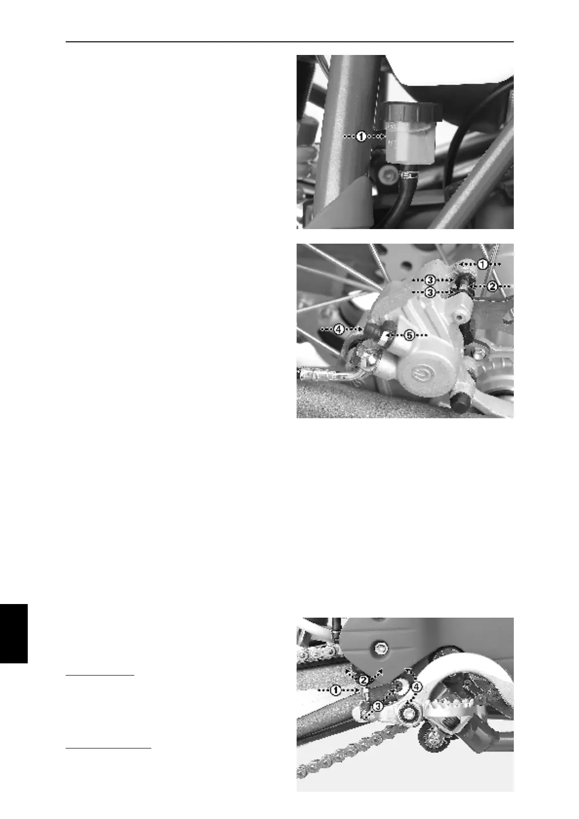
Always check the level of brake fluid in the
reservoir (Fig. 10P-1). The level has to be within
the MIN and MAX marks when the motorcycle is
upright.
Always check the brake hoses for any leakage
and/or deterioration.
Always check the wear of the brake pads. Change
the pads if the total thickness of each pad is less
than 1,5 mm, excluding the metal part.
Brake fluid:
Add fluid; DOT 4, by removing the cap on the
reservoir and the gasket. Take care - the fluid is
toxic and could also harm the surfaces of the
motorcycle.
Brake pads:
Remove the clip (Fig. 10Q-1) holding the brake
pad pin (Fig. 10Q-2).
Remove the two brake pads by removing the pin
and pulling the two pads out (Fig. 10Q-3).
Fit new pads in reverse order.
Air bleeding:
Remove the dust cap (Fig. 10Q-4) and ensure
that the air nipple (Fig. 10Q-5, wrench No.11) is
easily opened. With the nipple in closed position;
push the lever downwards a couple of times and
keep it under pressure the last time. Open the
nipple slightly and the brake lever, still under
pressure, will move downwards allowing any air,
and fluid, to run through the brakeline and nipple.
Before releasing the pressure onto the lever; close
the air nipple.
Repeat the steps until no more air is visible. Make
sure that the reservoir has enough fluid all the
time.
Fig.
10P
Fig.
10Q
Fig.
10R
Adjustment of brake lever:
The rear brake lever is easily adjusted into a
personal point of pressure and height of the lever.
Pressure point: release the lock nut (Fig. 10R-1,
wrench No.10) of the pushrod and turn the
pushrod into selected position (Fig. 10R-2).
Always keep a clearance in between the lever and
the point of pressure. Tighten the locknut.
Height of the lever: release the allen screw (Fig.
10R-3, allen key No. 4) and turn the eccentric
adjustment (Fig. 10R-4) into selected position.
Tighten the allen screw.