SERVICING THE INDIVIDUAL PARTS
D
12
CYLINDER HEAD
– Remove the chain tensioning rail.
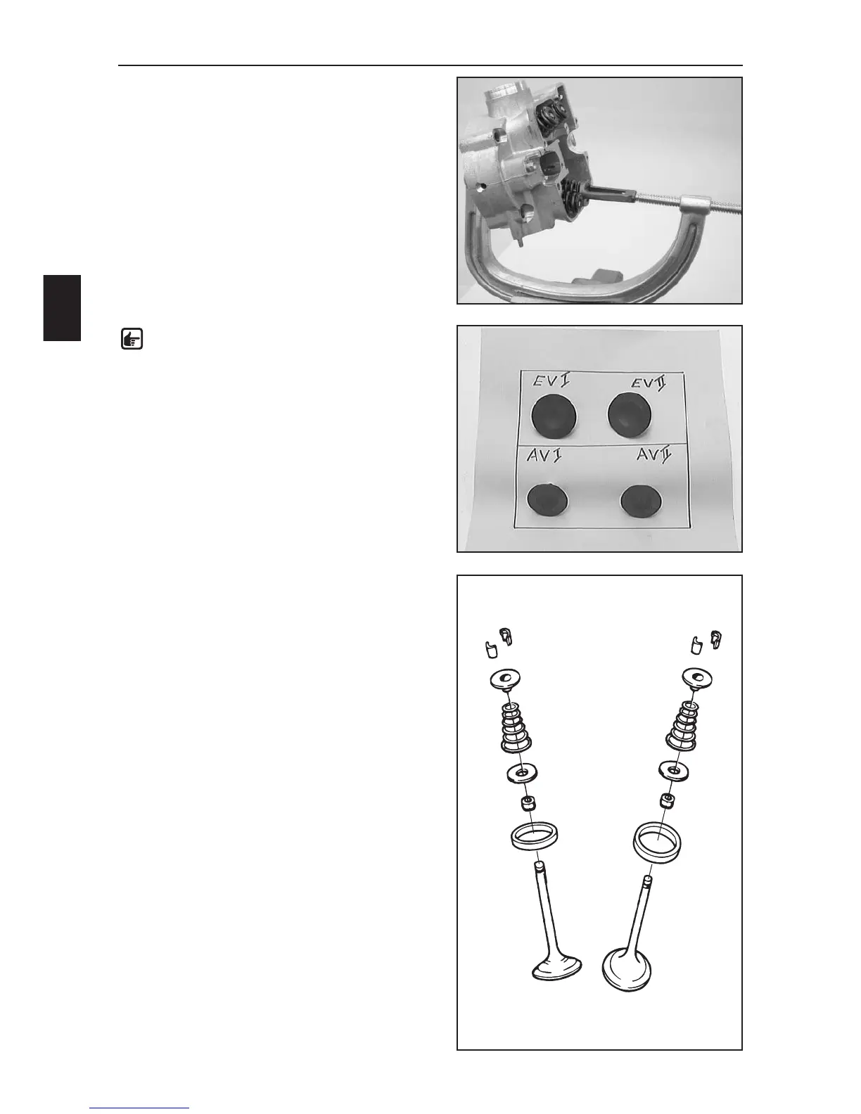
– Remove the 4 valves with the special tool
590.29.019.000.
NOTE: if you are mounting the used valves
again, they must be mounted in the same valve
guide as before. For this purpose, place the
valves in a box, marking the position they were
mounted in the cylinder head (see photo).
– Remove the valve spring retainer (1) and the valve
springs (2) from the cylinder head.
– Remove the spring retainer (3) and pull the valve shaft
seals (4) off of the valve guides.
Sealing area
Check the spark plug thread and the valve seats for
damage or cracks. Use a straight edge and a feeler
gauge to measure the sealing area to the cylinder for
distortion. Max. distortion 0.10 mm.
Valve seats
The valve seats may not be impacted. Width of sealing
seat: intake max. 1.50 mm; outlet max. 2.00 mm. Reseat
the valves if necessary.
Valves
Check the valve disk for wear and runout. The valve disk
runout should not exceed 0.05 mm. The valve seat may
not be impacted. The sealing area should be in the
middle of the valve seat. The valve shaft is hard-chrome-
plated. Wear usually occurs at the valve guide.
1
2
3
4
1
2
3
4