Do you have a question about the Husqvarna DM220 and is the answer not in the manual?
Details the scope and purpose of the workshop manual.
Explains the arrangement of text and illustrations within the manual.
Covers the content and purpose of the spares folder.
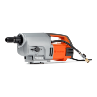
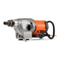
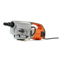
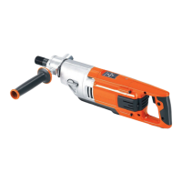
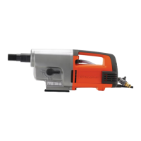
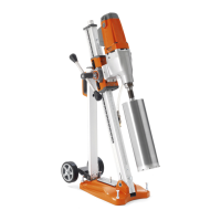
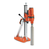
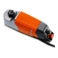
Lists and identifies the main components of the DM220.
Explains the differences between Type A and Type B models.
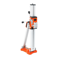
Provides advice on positioning the machine for service work.
Warns about electrical hazards and proper handling.
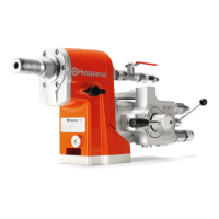
Explains the unit's role in water cooling or dust extraction.
Describes the unit's construction and O-ring seals.
Details the procedure for replacing casing and O-ring seals.
Outlines steps to separate the gear housing from the electric motor.
Details the process of removing the machine's handle halves.
Describes locating and removing the earth wire from the connector.
Steps to remove the cover for the stand mount and motor housing.
Details the separation of the gear housing from the gear box cover.
Explains how to drain the gearbox oil and its specifications.
Differentiates screw locations for Type A and Type B gear housing attachment.
Explains the transmission's role and components like slip clutch.
Outlines the necessity of dismantling the intermediate shaft first.
Provides steps for removing the intermediate shaft using a puller.
Describes the slip clutch and the initial steps for adjustment.
Details the importance of correctly installing spring washers for clutch force.
Explains when and how to replace the friction washer.
Guides on checking the condition of the gear wheel and its bushing.
Provides steps for adjusting the slip clutch torque on Type A models.
Details the slip clutch adjustment procedure for Type B models using specific tools.
Explains the spindle shaft's role and potential damage from mishandling.
States that the intermediate shaft must be removed first.
Details steps for removing circlips, gear wheels, and the gear knob.
Explains how to remove the wedge and lock ring using specific pliers.
Shows the gear housing after intermediate and spindle shaft parts are removed.
Describes the bearings and the seal cylinder in the spindle shaft.
Details removing circlips, pressing out the shaft and bearing.
Explains replacing the seal cylinder and fitting the bearing.
Lists required tools like bearing extractors, counter stay devices, and slide hammers.
Details the process for fitting needle bearings into the gear box cover.
Describes the procedure for fitting ball bearings into the gear housing.
Provides step-by-step instructions for replacing worn carbon brushes.
Explains how to check brush wear using a slide gauge.
Details how to remove and replace the carbon brush holder.
Illustrates the wiring within the handle for the 110V model.
Explains the terminal block connections for the mains cable.
Advises on routing cables to prevent damage during reassembly.
Shows the wiring within the handle for the 230V model.
Details terminal block connections for the 230V mains cable.
Guidance on checking the capacitor if the mains fuse blows.
Emphasizes care in routing cables to avoid crushing.
Explains the circuit board's functions like Softstart and Elgard.
Advises testing other components before replacing the circuit board.
Guides on correct sensor unit orientation for the spirit level.
Describes the electronic spirit level feature and its connections.
Details how to connect and disconnect the flat cable.
Illustrates specific cable connections to the circuit board and breaker.
Explains how to test the circuit breaker's interrupt and Smartstart functions.
Details how to test the Smartstart feature's resistance.
Discusses mains supply issues, cord replacement, and interference suppression.
Steps for accessing and preparing the rotor for testing.
Explains how to measure rotor inductance using a multimeter.
Details removing and replacing bearings on the rotor.
Specific instructions for replacing the bearing on the collector side.
Steps for replacing bearings in the gear box cover.
Guidance on pressing the rotor shaft into bearings, avoiding knocking.
Instructions for refitting the speed sensor with thread locker.
Explains how to check stator winding integrity using various measurements.
Describes Ohm and Henry measurements for stator testing.
Steps for removing and reinstalling the stator in the motor housing.
Lists specific tools available from Husqvarna for service operations.
Lists specialized tools not sold by Husqvarna but needed for service.
The Husqvarna DM 220 is a versatile drilling machine designed for both wet drilling with water cooling and dry drilling with dust extraction. It is primarily intended for professional use in construction and similar environments, offering robust construction and various features to enhance performance, safety, and ease of maintenance.
The DM 220's core function is drilling, facilitated by an electric motor that drives a spindle shaft through a multi-speed gear housing. The transmission system reduces the high speed of the electric motor to a lower speed suitable for the spindle shaft, with three gear selection positions controlled by a knob. An important safety feature is the slip clutch integrated into the intermediate shaft, which protects the operator in case of jamming. The machine also incorporates an electronic spirit level for guiding, a Softstart™ electronic current limiter for smoother starting, SmartStart® for reduced speed when the circuit breaker is pressed halfway, and Elgard™ as an electronic overload protection device.