Rev. 0308
9
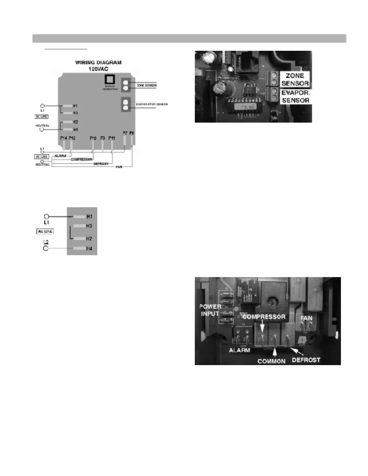
The wiring diagrams for the ERC 2 are shown below:
Fig. 7
208/240VAC
Fig. 8
For 208-240 VAC, change the jumpers on the
connectors located on the left side (from jumpers P3
to P4 and P5 to P6 for 120 VAC to a jumper from P4
to P5 for 208-240 VAC), just like this diagram shows.
Neutral becomes L2 in 208-240 VAC
WIRING INSTALLATION PROCEDURE
1. Accessing the terminals
• Open the metal case to access the control
connectors. The cable can be disconnected
from the display module while the control is
being wired. Reconnect the cable before using
the unit.
2. Connecting the sensors
• Connect the evaporator sensor to the lower
terminal block in the upper right corner.
• Connect the zone sensor to the upper
terminal block in the upper right corner.
Fig. 9 – Sensor Connectors
3. Connecting the refrigeration / defrost equipment
•Connect the wires from the compressor
(including the thermostat) to the
correspondent terminal on the bottom side of
the control (Fig. 10).
• Connect the defrost device (heater or hot gas
solenoid) to the terminal in the control (Fig.
10).
• Connect the wire from L1 - 120 VAC or 208-
240 VAC line - to the terminal marked as
“COM”.
• Connect also the fan wires to the terminals
marked as “FAN”.
•Use the alarm quick connects to connect an
alarm to the control, as shown in the picture.
Fig. 10 – Load / AC Input Connectors
4. Supplying Power to the Unit The power input
must be connected to the terminals on the left side
of the control (Fig. 10). Connect the 120 VAC L1
wire (or 208-240 VAC L1 wire) to the uppermost
terminal and the 120 VAC neutral (or 208-240 VAC
L2 wire) to the lowermost terminal.
Paragon ERC 2 Electronic Controller for Self Contained Cases Cont’d