Engineering
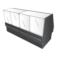
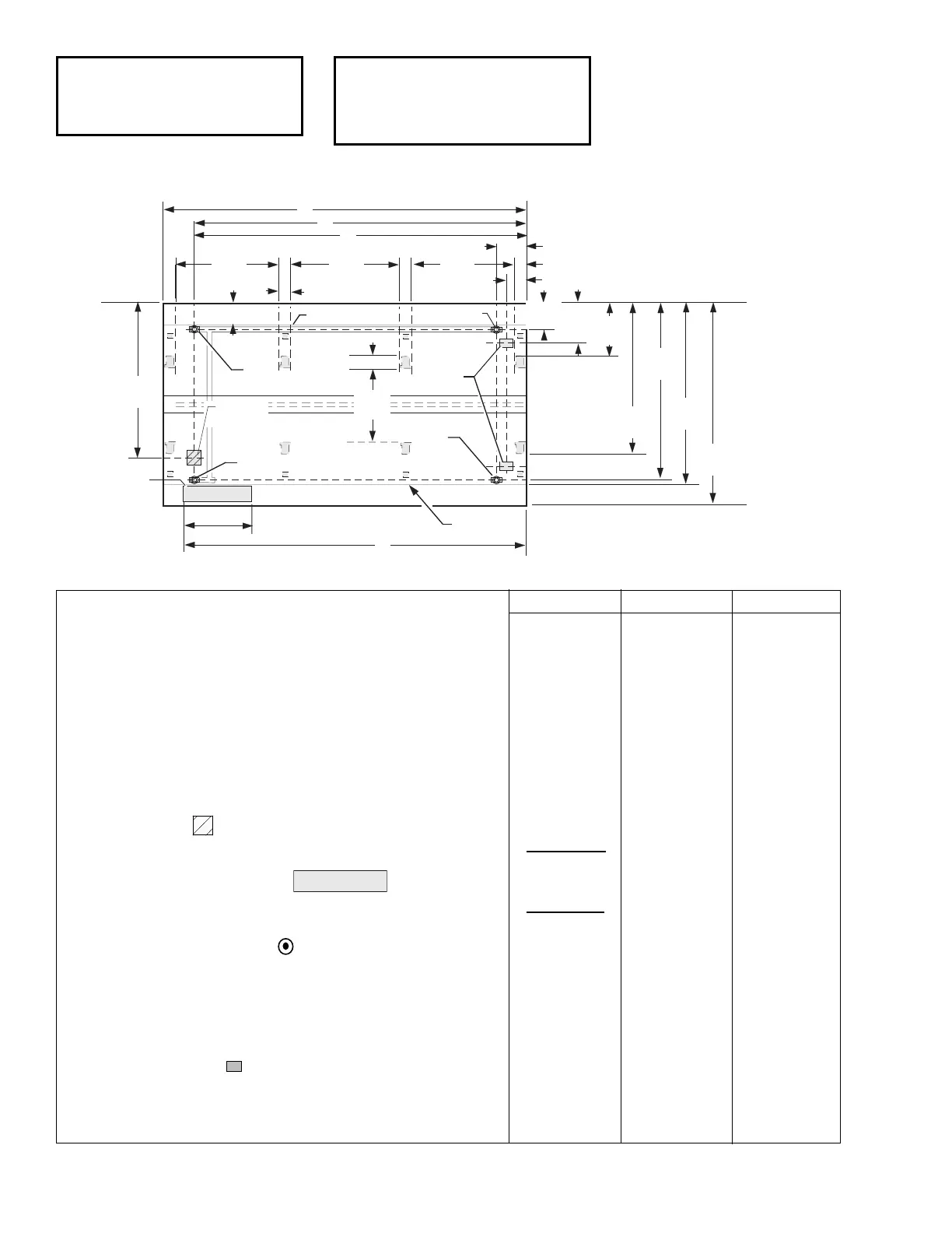
Plan Views
Dimensions shown as inches & (mm).
10-2004
4 ft 8 ft 12 ft
General
(A) Case Length (without ends or partitions) 48
1
/4 (1226) 96
3
/8 (2448) 144
1
/2 (3670)
(Each end and insulated partition adds 2 in. (51 mm) to case line up.)
Maximum O/S dimension of case back to front (includes bumper) 80
5
/8 (2046) 80
5
/8 (2046) 80
5
/8 (2046)
Back of case to front of splashguard 72 (1829) 72 (1829) 72 (1829)
Back of case to O/S edge of front leg 59
3
/4
(1515) 59
3
/4
(1515) 59
3
/4
(1515)
Distance between edges of external legs and center legs NA 41
1
/2 (1054) 41
1
/2 (1054)
Distance between edges of center legs NA NA 43
7
/8 (1114)
Distance between front legs and splashguard 12
3
/8 (312) 12
3
/8 (312) 12
3
/8 (312)
Electrical Service (Electrical Field Wiring connection point)
(B) RH End of case to center of stub up area 36
1
/8 (918) 84
1
/4 (2140) 132
3
/8 (3363)
Back of case to center of stub up area 64
1
/2 (1638) 64
1
/2 (1638) 64
1
/2 (1638)
Length of electrical wireway 26
1
/2 (673) 26
1
/2 (673) 26
1
/2 (673)
(C) RH End of case to LH end of wireway 40
1
/2 (1029) 90
1
/8 (2289) 138
1
/4 (3511)
Waste Outlets (One each end)
(D) RH End of case to the center of LH waste outlet 36
1
/8 (918) 84
1
/4 (2140) 132
3
/8 (3363)
RH End of case to the center of RH waste outlet 12
1
/8 (307) 12
1
/8 (307) 12
1
/8 (307)
Back O/S of case to center of waste outlets 70
1
/4 (1784) 70
1
/4 (1784) 70
1
/4 (1784)
Schedule 40 PVC drip pipe 1
1
/4 (32) 1
1
/4 (32) 1
1
/4 (32)
Refrigeration Outlet
Back of case to center of front refrigeration outlet 64
7
/8 (1646) 64
7
/8 (1646) 64
7
/8 (1646)
Back of case to center of rear refrigeration outlet 15
3
/4 (400) 15
3
/4 (400) 15
3
/4 (400)
RH end of case to center of refrigeration outlet 8 (203) 8 (203) 8 (203)
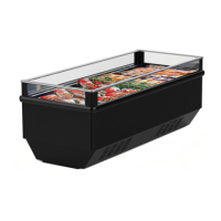
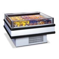
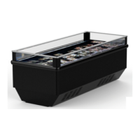
Low / MediumTemperature
Wide Island
 Loading...