REV B 4-12 117364
Procedure:
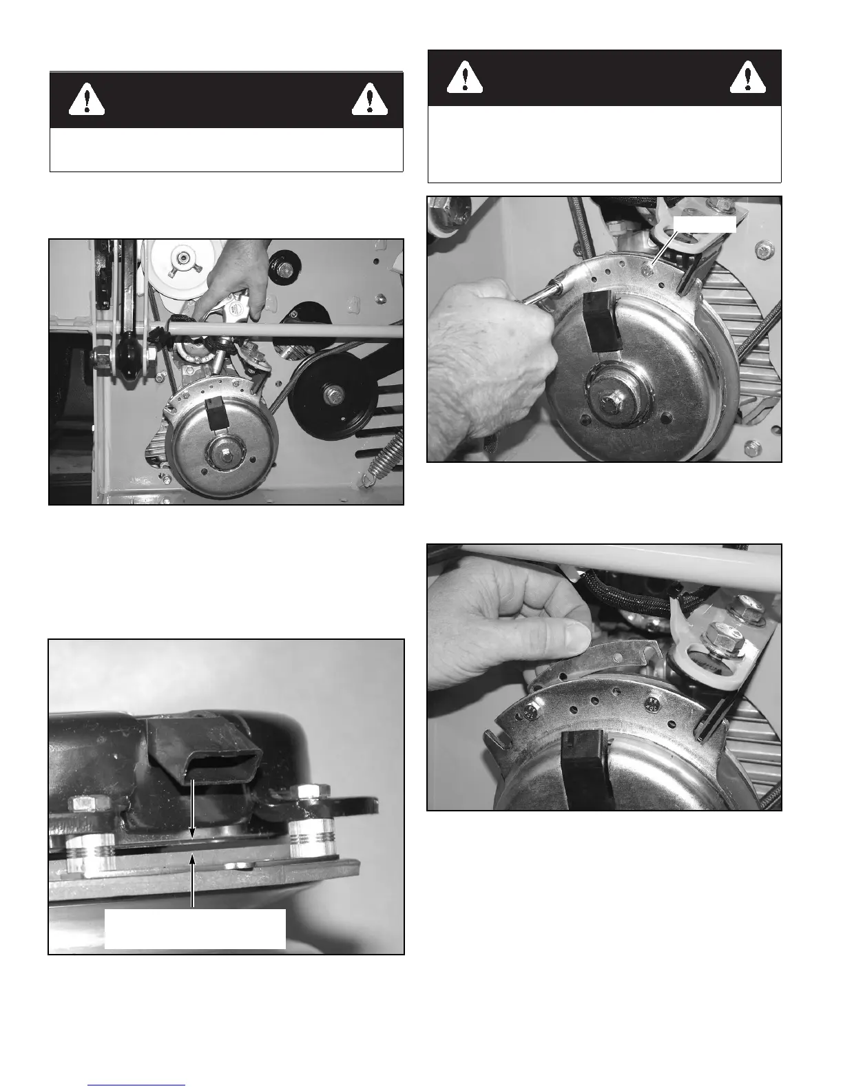
With engine off, key removed and clutch disengaged and
using a pneumatic line, blow out any debris from under the
brake pole and around the aluminum spacers. Figure 4-31
Check the air gap between rotor & armature with feeler gage.
If the gap is less than .070”, then follow the troubleshooting
procedure outlined in Warner Electric P1177 installation
troubleshooting guide available on Warner Electric’s web site-
www.Warnerelectric.com. If the air gap is over .070”, follow the
procedure outlined below. Figure 4-32
1. Loosen both brake mounting bolts 1/2 to 1 full turn as
shown in Figure 4-33.
2. Using needle nose pliers, or by hand, take hold of the tab
and remove shim (do not discard shim until proper clutch
function has been confirmed). Figure 4-34
3. Using a pneumatic line, blow out any debris from under
the brake pole and around the aluminum spacers. Figure
4-31
4. Re-torque each bolt (M6 X 1) to 120 in.-lbs.
5. Using a .015” thick feeler gage, verify that a gap is
present between the rotor and armature face on both ends
of the brake pole as shown. Figure 4-35 and Figure 4-36
a. If the gap is less than .015” the clutch must be
replaced
b. If sufficient gap is present, then proceed to safety
check outlined below.
Always wear adequate eye protection when servicing the
mower.
Figure 4-31
Figure 4-32
Be certain that the gap between the
rotor and armature face is greater
than .070” prior to shim removal.
Do not remove brake pole from field shell/armature. The
brake pole tracks match with the clutch brake and need to
continue to match after shim is removed to ensure proper
brake torque. Figure 4-30
Figure 4-33
Figure 4-34
 Loading...