117364 6-1 REV B
DECK ADJUSTMENTS
Deck Leveling
Center deck leveling
To level the center deck both side decks must be attached.
Leveling the center deck must be done in the following manner:
1. Check tire pressures to make certain they are properly
inflated before starting to level deck. The recommended
pressures are as follows:
Drive wheels . . . . . . . . . . 15 - 20 psi (103 - 138 KPa)
Front wheels. . . . . . . . . . . 20 - 25 psi (138 - 172 KPa)
2. Park the unit on a flat surface.
3. Raise the center deck and latch in the transport position.
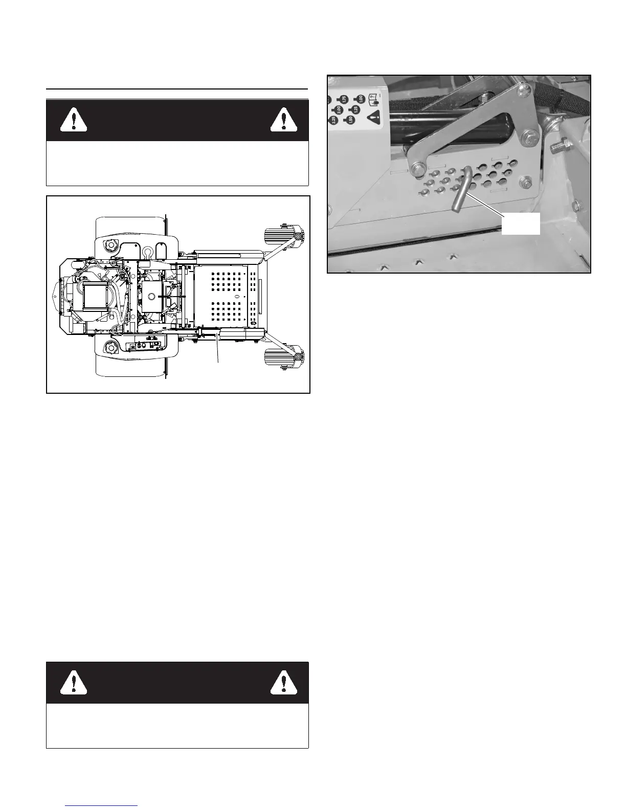
4. Place the height stop pin in the 3.25” (82.6 mm) hole.
Figure 6-2
5. Place 3” high deck support blocks (two stacked 2” x 4”
blocks can be used to create a 3” [76.2 mm] high support)
at the four corners of the center deck marked with the
locator triangle as shown. Figure 6-3 & Figure 6-4
6. Lower the center deck onto the 3” (76.2 mm) blocks.
7. Set the cutting height of the side decks at 3.25” (82.6
mm). Lower the side decks fully.
8. Make sure the deck stop is firmly against the height stop
pin. Figure 6-2
NOTE: The gas spring may keep block from contacting
the height stop pin.
If this occurs, place a 1/2” drive break-over bar and
extension into the square hole, in the deck lift linkage,
and use it to move the deck and force the block against
the height stop pin. Figure 6-5
9. Starting with the right front, adjust the nut on the deck lift
hangers until the deck begins to take the weight off of the
blocks. Then, repeat for the front left, rear right, and the
left rear deck lift hangers. After all four hangers have
been adjusted check to make sure that all four hangers are
tight. Figure 6-6
Side deck leveling
IMPORTANT: The center deck must be level before the
side decks can be leveled. Complete Center Deck Leveling sec-
tion before continuing with the Side Deck Leveling procedure.
Leveling the side decks must be done in the following
manner:
1. Check tire pressures to make certain they are properly
inflated before starting to level deck. The recommended
pressures are as follows:
Drive wheels. . . . . . . . . . . 15 - 20 psi (103 - 138 KPa)
Front wheels . . . . . . . . . . . 20 - 25 psi (138 - 172 KPa)
2. Park the unit on a flat surface.
3. Raise the center deck and latch in the transport position.
4. Place the height stop pin in the 3.25” (82.6 mm) hole.
The deck lift mechanism is under pressure. Use cau-
tion when performing deck adjustments or mainte-
nance. Figure 6-1
Figure 6-1
Stop engine. Make sure deck clutch switch is in the down
(OFF) position. Place control levers in the brake position
before leaving machine.
Figure 6-2
 Loading...