T
emperature and
Pressure Relief Valve
POWERFLOW
Hot
Drain Cock
To Drain (Waste)
P
ressure
(
Expansion)
Relief Valve
Expansion
Ve ss el
C
heck
V
alve
Balanced
Cold W ater
Draw O
Pressure
Reducing V alve
Service
Valve
Cold W ater
Mains
D
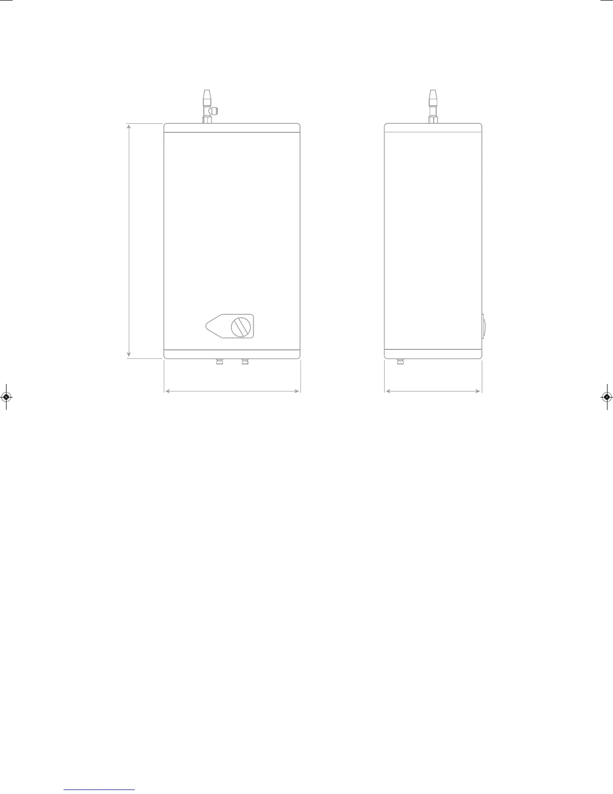
iagram 1
B
A
D
iagram 2
Model
V
ertical Bolt
Spacing A (mm)
H
orizontal Bolt
Spacing B (mm)
PF30L 270320
PF50L 520320
PF90L 430320
Safety Device
Tundish
600mm MAXIMUM
M
etal Discharge Pipe (D1) from
Temperature Relief to Tundish
Discharge Below
Fixed Grating
3
00mm MINIMUM
Metal Discharge Pipe (D2) from
Tundish with Continuous Fall
Fixed Grating
T
rapped Gully
Sizing of D2 Copper Discharge pipe for common temperature relief valve outlet size
Valve
o
utlet
size
M
inimum size of
discharge pipe (D1)
Minimum size of
d
ischarge pipe (D2)
from Tun di s h
M
aximum resistance allowed,
e
xpressed as a length of straight
pipe (I.E. no elbows or bends)
R
esistance
c
reated by each
elbow or bend
m8.0
m9
ot pu
mm22mm51
2/1
G
28mm up to 18m 1.0m
m4.1m72 ot *
mm53
Diagram 4
Element ange -
Remove to access anode
Thermostat
Thermal cutout -
Press here to reset
H
D
iagram 3
W D
 Loading...