5
D10-991-2400B
D/G-10 Installation
Important Precautions
Adequate Fluid Supply. To avoid cavitation and
premature pump failure, be sure that the pump will have
an adequate fluid supply and that the inlet line will not be
obstructed. See “Inlet Piping”.
Positive Displacement. This is a positive-displacement
pump. To avoid severe system damage if the discharge line
ever becomes blocked, install a relief valve downstream
from the pump. See “Discharge Piping”.
Safety Guards. Install adequate safety guards over
all pulleys, belts, and couplings. Follow all codes and
regulations regarding installation and operation of the
pumping system.
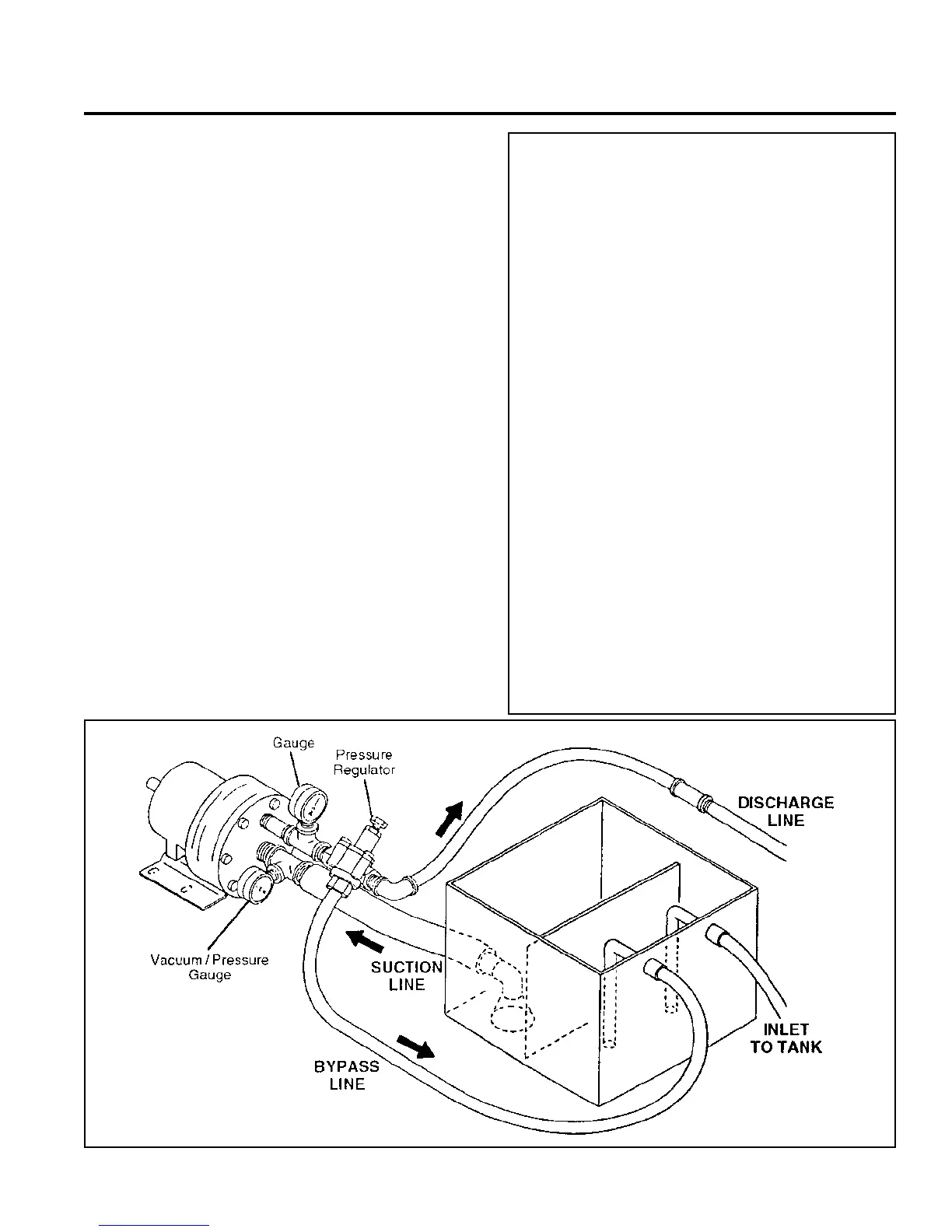
Shut-Off Valves. Never install shut-off valves between
the pump and discharge pressure regulator, or in the
regulator bypass line.
Freezing Conditions. Protect the pump from freezing.
See also the Maintenance Section.
Consult the Factory for the following situations:
• Extreme temperature applications – above 160° F. (71°
C) or below 40° F. (4.4° C)
• Pressure feeding of pumps
• Viscous or abrasive fluid applications
• Chemical compatibility problems
• Hot ambient temperatures – above 110° F. (43° C)
• Conditions where pump oil may exceed 200° F. (93° C)
because of a combination of hot ambient temperatures,
hot fluid temperature, and full horsepower load — an
oil cooler may be required
Location
Locate the pump as close to the supply source as possible.
Install it in a lighted clean space where it will be easy to inspect
and maintain. Allow room for checking the oil level, changing
the oil, and removing the pump head (manifold, valve plate and
related items).
Mounting
The pump shaft can rotate in either direction.
To prevent vibration, mount the pump and motor securely on
a level rigid base.
On a belt-drive system, align the sheaves accurately; poor
alignment wastes horsepower and shortens the belt and bearing
life. Make sure the belts are properly tightened, as specified by
the belt manufacturer.
On a direct-drive system, align the shafts accurately. Unless
otherwise specified by the coupling manufacturer, maximum
parallel misalignment should not exceed 0.015 in. (0.4 mm)
and angular misalignment should be held to 1° maximum.
Careful alignment extends life of the coupling, pump, shafts,
and support bearings. Consult coupling manufacturer for exact
alignment tolerances.